MAINTENANCE
PERIODIC MAINTENANCE
Any qualified repair shop or person may maintain, replace or repair the emission control devices or systems on your vehicle. An authorized POLARIS dealer can perform any service that may be necessary for your vehicle. POLARIS also recommends POLARIS parts for emissions-related service, however equivalent parts can be used.
It is a potential violation of the Clean Air Act if a part supplied by an aftermarket parts manufacturer reduces the effectiveness of the vehicle’s emission controls. Tampering with emission controls is prohibited by federal law.
Owners are responsible for performing the scheduled maintenance identified in this owner’s manual. Careful periodic maintenance will help keep your vehicle in safe, reliable condition. Inspect, clean, lubricate, adjust and replace parts as necessary. When inspection reveals the need for replacement parts, genuine POLARIS parts are available from your POLARIS dealer. Equivalent parts may be used for emissions-related service.
Record maintenance and service in the Maintenance Log beginning on page
249. Service and adjustments are important for proper vehicle operation. If you’re not familiar with safe service and adjustment procedures, a qualified dealer can perform these operations. Maintenance intervals in the following chart are based upon average riding conditions and an average vehicle speed of approximately 10 mph (16 km/h). Vehicles subjected to severe use must be inspected and serviced more frequently.
SEVERE USE DEFINITION
Severe use is defined as:
- Frequent immersion in mud, water, or sand
- Frequent or prolonged operation in dusty environments
- Short trip cold weather operation
- Racing or racing-style high RPM use
- Prolonged low speed, heavy load operation
- Extended idle
POLARIS MAINTENANCE SCHEDULE
The intervals shown are based on vehicles operated under normal conditions.
Each interval is given in hours and miles (kilometers). Items should be serviced at whichever interval comes first.
Continue to reference the following maintenance schedules at the given intervals as hours and miles (kilometers) increase on the vehicle.
Vehicles subjected to severe use must be serviced at 50% of the stated interval. Examples of Severe Use: Frequent immersion in mud, water, or sand, constant high RPM use, prolonged low-speed heavy load operation, extended idle, and short trip cold weather operation.
INITIAL BREAK-IN SERVICE FIRST 25 HOURS / 500 MILES (800 KM)
| Brake System | Initial fluid level inspection; inspect for fluid leaks; add recommended brake fluid from a sealed container if needed. Inspect brake pad wear. |
| Engine Oil and Filter | Change the engine oil and filter. |
| Front Gearcase Fluid | Change fluid. |
| Transmission Fluid | Initial fluid level inspection; inspect for fluid leaks; add lubricant if needed. |
| The break-in period consists of the first 25 hours of operation. Careful treatment of a new engine and drive components will result in more efficient performance and longer life for these components. The items outlined in this service interval only need to be performed at the first 25 hours of operation. They do not need to be performed every 25 hours. | |
Vehicles subjected to severe use must be serviced at 50% of the stated interval. Examples of Severe Use: Frequent immersion in mud, water, or sand, constant high RPM use, prolonged low-speed heavy load operation, extended idle, and short trip cold weather operation.
EVERY 100 HOURS / 1000 MILES (1600 KM) OR YEARLY
| Air Filter | Replace air filter. Ensure proper installation of filter and airbox cover. Inspect ducts and screens; clean as necessary. |
| Battery | Check terminals; terminals should be tight and free of corrosion. Clean, test, and replace as necessary. |
| Body to Frame Fasteners | Inspect; tighten as needed. |
| Brake Pad Wear | Inspect; replace as needed. |
| Clutches (Non-EBS)* | Inspect bushings, rollers, wearable parts; clean; replace worn parts. |
| Cooling System | Fluid level inspection; inspect for fluid leaks; add coolant if needed. Inspect coolant strength seasonally; pressure test system yearly. |
| Drive Belt | Inspect; replace as needed. |
| Engine Breather | Inspect; clean; replace if necessary. |
| Exhaust Silencer / Pipe | Inspect for leaks or damage. |
| Front Gearcase Fluid | Check fluid. |
| Fuel System* | Cycle key to pressurize fuel pump; check for leaks at fuel system connections, check for leaks at fill cap. |
| General Lubrication | Locate all applicable fittings and grease. |
| Spark Arrestor | Clean out. |
| Suspension Components* | Inspect tie rods, wheel bearings, suspension bushings, and ball joints for loose or worn components; replace as needed. Inspect shock absorbers for leaks or damage. |
| Temporary Brake Lock | Inspect and adjust brake fluid level as needed. |
| Throttle Cable (if applicable)* | Inspect; adjust; replace if necessary. |
EVERY 100 HOURS / 1000 MILES (1600 KM) OR YEARLY
| Transmission Fluid | Check fluid. |
| Wiring | Inspect for wear, routing, and retention. |
| * Have an authorized Polaris dealer or other qualified person perform these services. | |
Vehicles subjected to severe use must be serviced at 50% of the stated interval. Examples of Severe Use: Frequent immersion in mud, water, or sand, constant high RPM use, prolonged low-speed heavy load operation, extended idle, and short trip cold weather operation.
ADDITIONAL MAINTENANCE INTERVALS
| Every 200 hours / 2000miles (3200 km) | Clutches (EBS)* | Inspect bushings, rollers, wearable parts; clean; replace worn parts. |
| Engine Oil and Filter | Change the engine oil and filter. | |
| Front Gearcase Fluid | Change fluid. | |
| Shock Absorbers* | Inspect; replace or rebuild (if applicable) as needed. | |
| Spark Plugs | Inspect; replace as needed. | |
| Transmission Fluid | Change fluid. | |
| Every 500 hours / 5000miles (8000 km) | Valve Clearance* | Inspect; adjust as needed. |
| At 5000 miles (8000 km) | Spherical Exhaust Gaskets | Inspect for leaks or damage. Replace as necessary. |
| Every 24 months / 2 years | Brake Fluid | Change fluid. |
| Every 60 months / 5 years | Coolant | Change fluid. |
| * Have an authorized Polaris dealer or other qualified person perform these services. | ||
ELEVATING THE VEHICLE FOR SERVICE
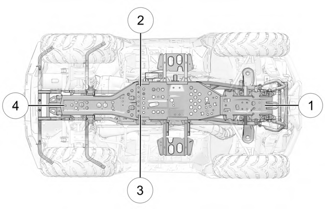
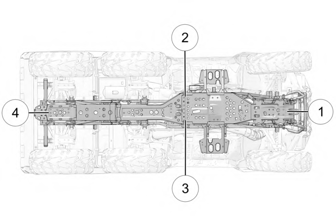
Some service procedures require elevation of the vehicle. Always position the vehicle on a firm, level surface before elevating. Do not position a jack or jack stand under any components other than the frame.
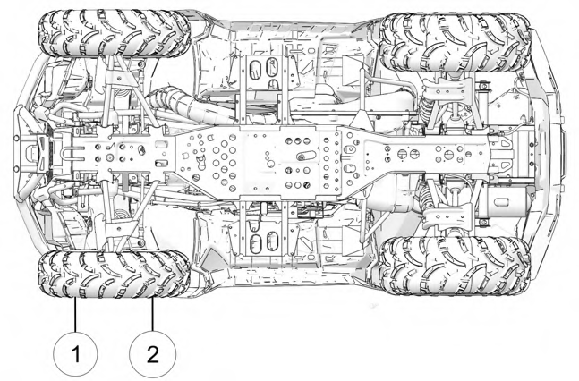
Use an appropriate lift or floor jack. Place the floor jack at the front (or rear) of the vehicle, directly under the center of the unit. Make sure the floor jack makes contact only with the frame of the vehicle while lifting q, w, e, and r.
Do not allow the vehicle to remain elevated on a floor jack. After elevating, place jack stands under the frame on each side of the floor jack, then lower the floor jack.
SPORTSMAN TOURING 570 / SPORTSMAN X2 570
SPORTSMAN 6X6 570
LUBRICATION GUIDE
Check and lubricate all components at the intervals outlined in the Polaris Maintenance Schedule. Items not listed in the chart should be lubricated at the General Lubrication interval.
The a-arms and lower control arms are lubricated at the factory, and no additional lubrication will be needed.
| ITEM | LUBE | CAPACITY | INSPECTION PROCEDURE |
| Engine Oil | PS-4 5W-50 4-CycleOil | 2 qt (1.9 L) | Maintain the oil level between the full and add lines on the dipstick. |
| Brake Fluid | DOT 4 Brake Fluid | – | Maintain the fluid level between the fill lines. |
| Transmission Fluid | AGL | 32 fl oz (948 mL) | Maintain the fluid level at the bottom of the fill hole threads. |
| Front Gearcase Fluid | Demand Drive Fluid | 9 fl oz (265 mL) | Maintain the fluid level at the bottom of the fill hole threads. |
| Front Prop Shaft | U-Joint Grease | – | Grease fittings (3 pumps maximum) every 500 miles (800 km), before long periods of storage, or after pressure washing or submerging. |
ENGINE OIL

Vehicle operation with insufficient, deteriorated, or contaminated engine oil will cause accelerated wear and may result in engine seizure, accident and injury.
WARNING
Always check and change the engine oil at the intervals outlined in the Polaris Maintenance Schedule. Always use the recommended engine oil.
Pay special attention to the oil level. A rise in oil level during cold weather can indicate contaminants collecting in the oil sump or crankcase. Change oil immediately if the oil level begins to rise. Monitor the oil level, and if it continues to rise, discontinue use and determine the cause. Your authorized dealer can assist.
OIL RECOMMENDATIONS
Always change the oil filter when you change the engine oil.
IMPORTANT
POLARIS recommends the use of POLARIS PS-4 Full Synthetic 5W-50 4-cycle oil or a similar oil for this engine. Oil may need to be changed more frequently if POLARIS oil is not used. Always use 5W-50 oil. Follow the manufacturer’s recommendations for ambient temperature operation.
See the Lubrication Guide section for fluid recommendations and capacities.
Mixing brands or using a non-recommended oil may cause serious engine damage. Always use the recommended oil. Never substitute or mix oil brands.
IMPORTANT
OIL LEVEL CHECK
Check the oil level when the engine is cold. Never check the oil with the engine running or damage to the dipstick and / or engine could occur.
IMPORTANT
- Position the vehicle on a level surface. Put the transmission in PARK (P) and lock the temporary brake lock. Turn the engine off.
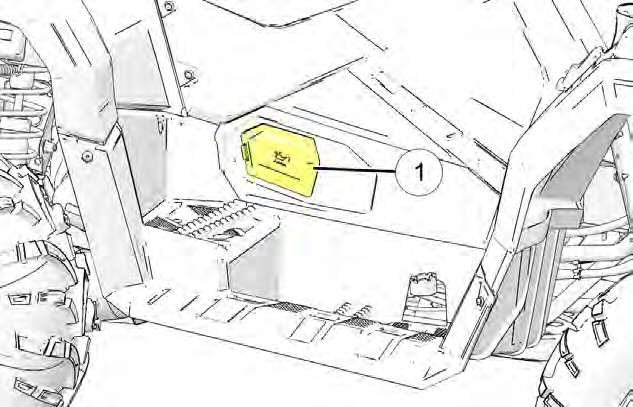
- Remove the engine access panel q on the right side of the vehicle.
- Clean the area around the dipstick.
- With the engine off, remove the dipstick. Wipe it dry with a clean cloth.
- Install the dipstick and tighten it all of the way to ensure an accurate measurement.
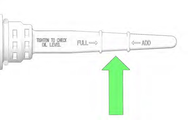 Remove the dipstick and check the oil level. The oil level should be between the full and add lines on the dipstick.
- If needed, use a funnel to slowly add the recommended oil as indicated by the level on the dipstick. Do NOT overfill.
- Install the dipstick and the engine access panel.
OIL AND OIL FILTER CHANGE
Always change the oil filter when you change the engine oil.
IMPORTANT
The engine oil and oil filter should be changed in accordance with the Polaris Maintenance Schedule. See the Lubrication Guide section for fluid recommendations and capacities.
- Position the vehicle on a level surface. Put the transmission in PARK (P) and lock the temporary brake lock.
- Clean the area around the drain plug q.
- Put a drain pan below the drain plug.
- Remove the drain plug q and washer w. Allow the oil to drain completely.

Hot oil can cause burns to skin. Do not allow hot oil to contact skin.
CAUTION
- Install a new sealing washer on the drain plug.
The sealing surfaces on the drain plug must be clean and free of burrs, nicks, and scratches.
NOTICE
- Install the drain plug and torque to specification.
Oil Drain Plug:
13 ft-lbs (18 N·m)
TORQUE
- Put a drain pan below the oil filter e.
- Use an Oil Filter Wrench (available from your POLARIS dealer) to turn the oil filter counter-clockwise to remove it.
Oil Filter Wrench
PU-50105
- Use a clean dry cloth to clean the oil filter sealing surface on the engine crankcase.
- Lubricate the o-ring on the new oil filter with a film of fresh oil. Check to make sure the o-ring is in good condition.
- Install the new oil filter and rotate it clockwise by hand until the filter gasket contacts the sealing surface, then turn it an additional 3/4 turn.
- Remove the engine access panel r on the right side of the vehicle.

- Clean the area around the dipstick.
- Remove the dipstick. Use a funnel to slowly add the recommended oil to bring the oil level between the full and add lines on the dipstick. Do NOT overfill.
Recommended Lubricant: PS-4 5W-50 4-Cycle Oil Capacity:
2 qt (1.9 L)
FLUID CAPACITY
- Install the dipstick.
- Start the engine. Allow it to idle for one to two minutes.
- Stop the engine and check for leaks.
- Check the oil level. Add oil as needed. See page 136.
- Install the engine access panel.
- Discard the used oil and oil filter properly.
TRANSMISSION FLUID
Images are for reference only. Your model might differ slightly.
NOTICE
The transmission fluid should be checked and changed in accordance with the Polaris Maintenance Schedule. See the Lubrication Guide section for fluid recommendations and capacities. Maintain the fluid level at the bottom of the fill plug hole. The fill plug is located on the left side of the vehicle behind the footwell. The drain plug is located on the right side of the vehicle.
FLUID CHECK
- Position the vehicle on a level surface. Put the transmission in PARK (P) and lock the temporary brake lock.
- Remove the rear left wheel. See page 169.
- Clean the area around the fill plug. Remove the fill plug and check the fluid level. The fluid level is correct if fluid is visible at the fill hole threads.

- If needed, use a funnel to slowly add the recommended fluid to bring the level to the bottom of the fill hole threads.
- Clean any dirt or debris on the fill plug. Inspect the o-ring and replace if necessary.
- Install the fill plug and torque to specification.
Transmission Drain / Fill Plug:
12 ft-lbs (16 N·m)
TORQUE
- Clean any residual fluid off of the vehicle and inspect for leaks.
- Install the rear left wheel. See page 170.
FLUID CHANGE
- Position the vehicle on a level surface. Put the transmission in PARK (P) and lock the temporary brake lock.
- Properly lift and elevate the vehicle.

Use caution when you lift the vehicle off of the ground. If the vehicle is not properly lifted and supported, serious injury or death could result from the vehicle coming off of the supports or hoist. Always follow the instructions of the equipment being used and make sure it is sufficiently rated for the vehicle being lifted.
WARNING
- Remove the rear right wheel. See page 169.
- Clean the area around the drain plug.
- Put a drain pan below the drain plug.
 Remove the drain plug and allow the fluid to drain completely. Discard the used fluid properly.
- Clean any dirt or debris on the drain plug. Inspect the o-ring and replace if necessary.
- Install the drain plug and torque to specification.
Transmission Drain / Fill Plug:
12 ft-lbs (16 N·m)
TORQUE
- Install the rear right wheel. See page 170.
- Remove the rear left wheel.
 Remove the fill plug.
- Use a funnel to slowly add the proper amount of the recommended fluid. The fluid level should reach the bottom of the fill hole threads.
Recommended Lubricant:
AGL
Capacity:
32 fl oz (948 mL)
FLUID CAPACITY
- Clean any dirt or debris on the fill plug. Inspect the o-ring and replace if necessary.
- Install the fill plug and torque to specification.
Transmission Drain / Fill Plug:
12 ft-lbs (16 N·m)
TORQUE
- Clean any residual fluid off of the vehicle and inspect for leaks.
- Install the rear left wheel.
FRONT GEARCASE (DEMAND DRIVE) FLUID
The front gearcase fluid should be checked and changed in accordance with the Polaris Maintenance Schedule. See the Lubrication Guide section for fluid recommendations and capacities.
Change the front gearcase fluid every 25 hours if the ADC unit is exposed to extreme use. Extreme use includes any of the following:
- operation in ADC mode for prolonged periods
- constant ADC operation on hilly or mountainous terrain
- ADC is the primary mode of all-wheel-drive operation
If the front gearcase is makes excessive noise during ADC operation, change the demand drive fluid. If the noise continues, please see your POLARIS dealer or other qualified service facility for service.
NOTICE
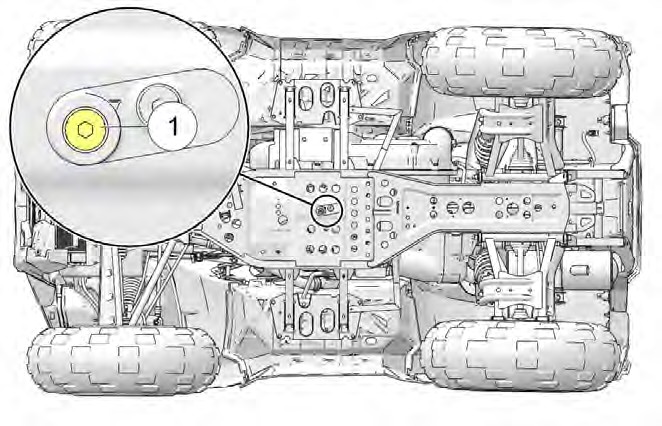
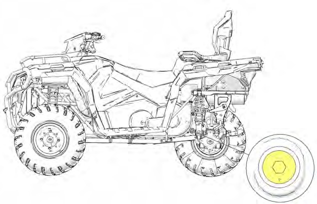
Use the recommended fluid. Use of other fluids may result in improper operation of components. Maintain the fluid level at the bottom of the fill hole threads. The fill plug is located on the right side of the front gearcase. The drain plug is located on the bottom of the front gearcase and can be accessed through the bottom of the chassis.
FLUID CHECK
- Position the vehicle on a level surface. Put the transmission in PARK (P) and lock the temporary brake lock.
- Clean the area around the fill plug q.
- Remove the fill plug and check the fluid level. The fluid level is correct if fluid is visible at the fill hole threads.
- If needed, use a funnel to slowly add the recommended fluid to bring the level to the bottom of the fill hole threads.
- Clean any dirt or debris on the fill plug. Inspect the o-ring and replace if necessary.
- Install the fill plug and torque to specification.
Front Gearcase Drain / Fill Plug:
19 ft-lbs (26 N·m)
TORQUE
- Clean any residual fluid off of the vehicle and inspect for leaks.
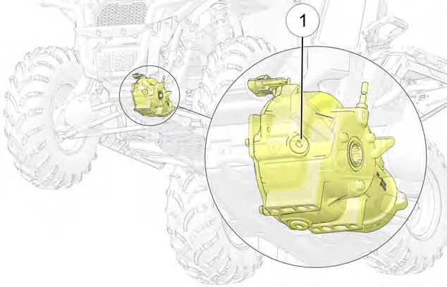
FLUID CHANGE
- Position the vehicle on a level surface. Put the transmission in PARK (P) and lock the temporary brake lock.
- Clean the area around the drain plug w.
- Put a drain pan below the drain plug.
- Remove the drain plug and allow the fluid to drain completely. Discard the used fluid properly.
- Clean any dirt or debris on the drain plug. Inspect the o-ring and replace if necessary.
- Install the drain plug and torque to specification.
Front Gearcase Drain / Fill Plug:
19 ft-lbs (26 N·m)
TORQUE
- Clean the area around the fill plug.
- Remove the fill plug.
- Use a funnel to slowly add the proper amount of the recommended fluid. The fluid level should reach the bottom of the fill hole threads.
Recommended Lubricant: Demand Drive Fluid Capacity:
9 fl oz (265 mL)
FLUID CAPACITY
- Clean any dirt or debris on the fill plug. Inspect the o-ring and replace if necessary.
- Install the fill plug and torque to specification.
Front Gearcase Drain / Fill Plug:
19 ft-lbs (26 N·m)
TORQUE
- Clean any residual fluid off of the vehicle and inspect for leaks.
POWER STEERING UNIT
If your model is equipped with power steering, frequently clean the areas around and on the power steering unit to allow proper cooling. Clean these areas thoroughly.
STEERING ASSEMBLY
The steering assembly of the ATV should be checked periodically for loose nuts and bolts. If loose nuts and bolts are found, see your authorized dealer or other qualified service facility before operating the vehicle.
COOLING SYSTEM
The engine coolant level is controlled, or maintained, by the recovery system. The recovery system components are the recovery bottle, the radiator filler neck, the radiator pressure cap and the connecting hose.
As coolant operating temperature increases, the expanding (heated) excess coolant is forced out of the engine, past the pressure cap, and into the recovery bottle. As engine coolant temperature decreases the contracting (cooled) coolant is drawn back up from the bottle, past the pressure cap, and into the radiator.
Some coolant level drop on new vehicles is normal as the system is purging itself of trapped air. Check the coolant level and maintain as recommended by adding coolant to the recovery bottle.
POLARIS recommends the use of POLARIS Antifreeze 50/50 Premix. This antifreeze is already premixed and ready to use. Do not dilute with water. See the Polaris Products section for the part numbers.
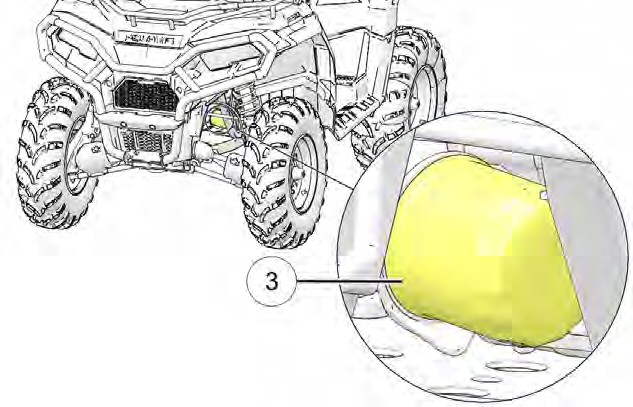
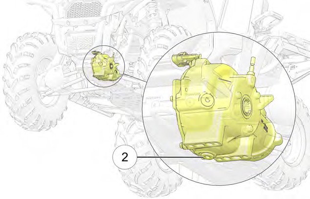
RECOVERY BOTTLE COOLANT
The recovery bottle is located under the front cab and can be accessed through the front right wheel well.
- View the fluid level in the bottle.
- If the level is low, remove the bottle cap and add coolant as needed. Maintain the coolant level between the minimum and maximum marks on the bottle (when the fluid is cool).
- Install the bottle cap.
Image is for reference only. Your model might differ slightly.
NOTICE
RADIATOR COOLANT
To ensure that the coolant maintains its ability to protect the engine, we recommend that the system be completely drained every five (5) years and fresh Antifreeze 50/50 Premix added.
Any time the cooling system has been drained for maintenance or repair, replace the coolant with fresh Antifreeze 50/50 Premix. If the recovery bottle has run dry, check the level in the radiator. Add coolant as needed.

Escaping steam can cause burns. Never remove the pressure cap while the engine is warm or hot. Always allow the engine to cool before removing the pressure cap.
CAUTION
 Open the front rack.
- Locate the radiator cap access cover q and open cover.
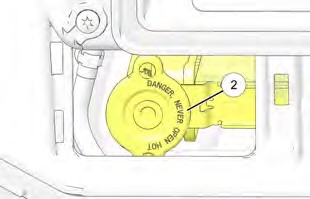 Remove the pressure cap w.
- Use a funnel to slowly add the proper amount of recommended coolant through the radiator filler neck.
- Install the pressure cap. Use of a non-standard pressure cap will not allow the recovery system to function properly. Your POLARIS dealer can provide the correct replacement part.
- Close the radiator cap access cover and front rack.
BRAKES
HAND BRAKE

Brake discs can become extremely hot after operation. Allow the discs to cool before performing maintenance to prevent risk of burns.
CAUTION
The front and rear brakes are hydraulic disc brakes, activated by moving the single brake lever toward the handlebar. These brakes are self- adjusting.
Under normal operation, the diaphragm extends into the reservoir as fluid level drops. If the fluid level is low and the diaphragm is not extended, a leak is likely and the diaphragm should be replaced. To ensure proper diaphragm operation, always fill the reservoir as needed whenever the cover is loosened or removed. Do not overfill.

An over-full master cylinder may cause brake drag or brake lock- up, which could result in serious injury or death. Maintain brake fluid at the recommended level. Do not overfill.
WARNING
The following checks are recommended to keep the brake system in good operating condition. Check more often if brakes are used heavily under normal operation.
-
- Always keep brake fluid at an adequate level. See the Master Cylinder/Brake Fluid section for details.
- Check the brake system for fluid leaks.
- Check the brakes for excessive travel or spongy feel.
- Check the friction pads for wear, damage and looseness. Replace brake pads when they are worn to .030” (0.762 mm).
- Check the security and surface condition of the disc. Clean any grease using a recommended brake cleaner or alcohol. Do not use spray lubricants or other petroleum-based products. If you discover any damage (cracks, excessive corrosion, warping) see your dealer for service before operating.
AUXILIARY FOOT BRAKE
The hydraulic auxiliary brake system requires no adjustment. Check the brake fluid level frequently for the auxiliary brake system.
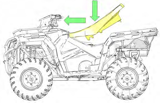
SEAT REMOVAL
TOURING MODELS
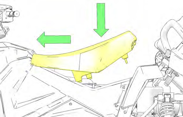
- Pull up on the passenger seat latch lever q.
- Tilt the passenger seat forward and then lift up to remove the seat from the vehicle.
- Lift the rear of the driver seat and slide the seat towards the back of the vehicle to remove it.
X2 MODELS
- Pull up on one of the cargo box latch levers q and tilt the cargo box backwards.
- Lift the rear of the driver seat and slide the seat towards the back of the vehicle to remove it.
The rear seat can be adjusted to three different positions. See page 51 for details.
NOTICE
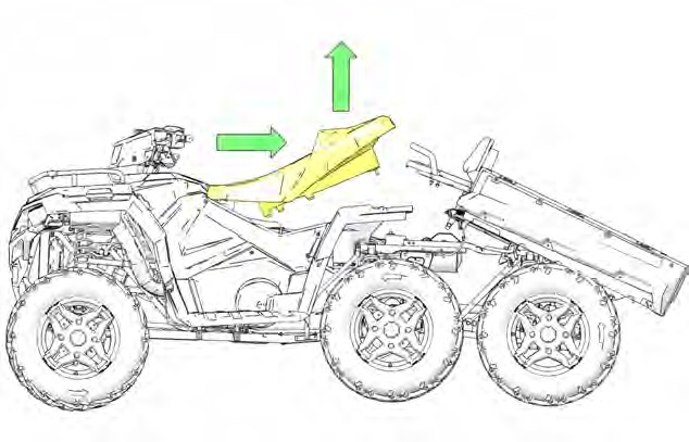
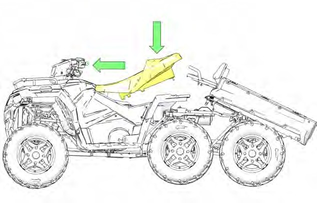
6X6 MODELS
-
 Lift up on the cargo box release lever q on either side of the vehicle and tilt the cargo box backwards.
- Lift the rear of the driver seat and slide the seat towards the back of the vehicle to remove it.
SEAT INSTALLATION
TOURING MODELS
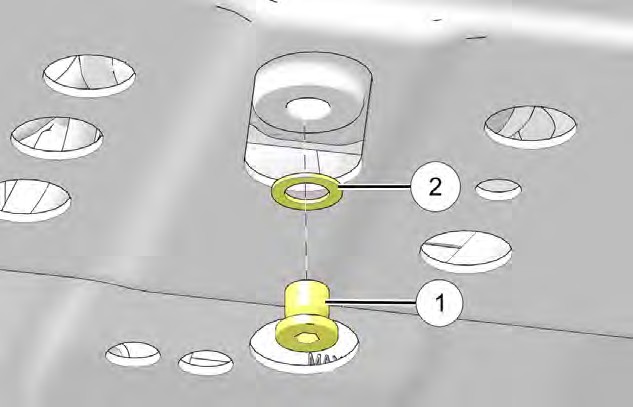
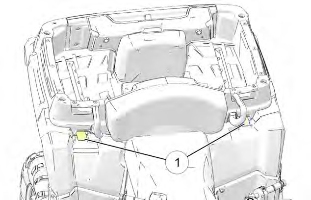
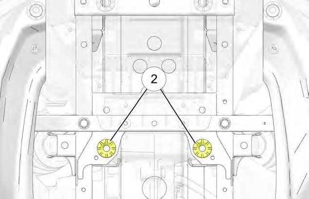
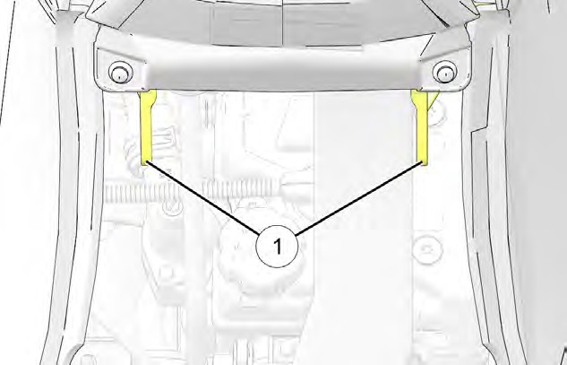 Align the two openings in the bottom of the driver seat with the two seat base brackets q.
- Slide the driver seat forward and lower the rear.
- Press the rear of the driver seat down firmly to seat the two pins into the grommets w.
- Install the passenger seat onto the vehicle by pushing back on the backrest and down on the passenger seat latch lever e until you feel and hear a click.
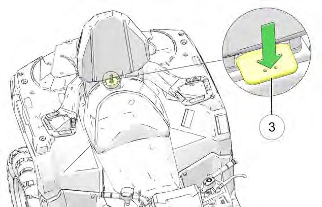
Make sure you push the passenger seat latch lever all of the way down so that it latches into place.
NOTICE
X2 MODELS
-
- Slide the driver seat forward and lower the rear.
-
- Tilt the cargo box to the upright position.
6X6 MODELS
- Slide the driver seat forward and lower the rear.
- Tilt the cargo box to the upright position.
SIDE PANEL / FOOTWELL REMOVAL
LEFT SIDE PANEL / FOOTWELL
-
- Remove the seat.
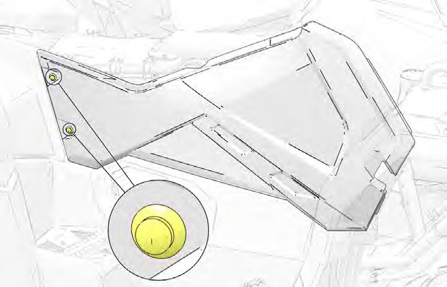
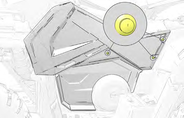 Use the multi-function pliers (included in your vehicle’s toolkit) to remove the three push rivets from the side panel / close off panel.
- Grasp the rear of the side panel. With a firm motion, pull the side panel outward to disengage the side panel / close off panel from the vehicle.
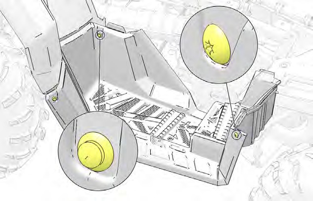 Remove the two screws and two push rivets from the footwell.
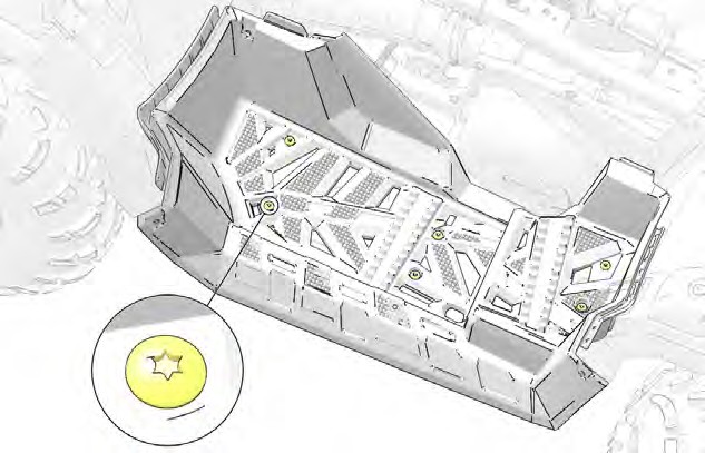
- Remove the six screws and nuts from the bottom of the footwell. Pull the footwell downward and outward to remove it.
RIGHT SIDE PANEL / FOOTWELL
-
-
- Remove the seat.
 Use the multi-function pliers (included in your vehicle’s toolkit) to remove the two push rivets from the side panel.
- Grasp the rear of the side panel. With a firm motion, pull the side panel outward to disengage it from the vehicle.
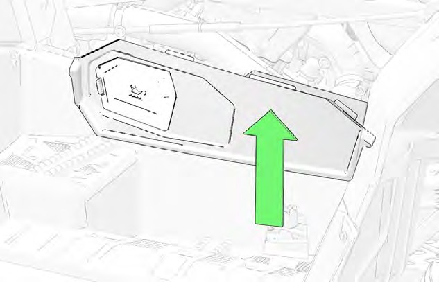
- Lift the close off panel / shield out of the vehicle.
-
The engine access panel is also removed.
NOTICE
-
-
- Remove the two screws and two push rivets from the footwell.
- Remove the six screws and nuts from the bottom of the footwell. Pull the footwell downward and outward to remove it.
-
SIDE PANEL / FOOTWELL INSTALLATION
LEFT SIDE PANEL / FOOTWELL
- Install the footwell onto the vehicle. Loosely install the six screws and nuts into the bottom of the footwell.
Observe the condition of each push rivet and check for damage. If damaged, POLARIS recommends that you replace the push rivet before installation.
NOTICE
- Loosely install the two screws and two push rivets into the footwell.
- Install the side panel / close off panel onto the vehicle and install the three push rivets.
- Install the seat.
- Torque all fasteners to specification.
Footwell to Chassis Fasteners: 3 in-lbs (4 N·m)
Footwell to Rear Cab Screws:
Torque Until Fully Seated
TORQUE
RIGHT SIDE PANEL / FOOTWELL
- Install the footwell onto the vehicle. Loosely install the six screws and nuts into the bottom of the footwell.
Observe the condition of each push rivet and check for damage. If damaged, POLARIS recommends that you replace the push rivet before installation.
NOTICE
- Loosely install the two screws and two push rivets into the footwell.
- Install the close off panel / shield onto the vehicle.
- Install the side panel onto the vehicle and install the two push rivets.
- Install the seat.
- Torque all fasteners to specification.
Footwell to Chassis Fasteners: 3 in-lbs (4 N·m)
Footwell to Rear Cab Screws:
Torque Until Fully Seated
TORQUE
TIRES

Operating your ATV with worn tires, improperly inflated tires, non-standard tires or improperly installed tires will affect vehicle handling and could cause an accident resulting in serious injury or death. Always follow all tire maintenance procedures as outlined in this manual and on the labels on the vehicle. Always use original equipment size and type when replacing tires.
WARNING
Refer to the specifications section for recommended tire type, size and pressure.
TIRE TREAD DEPTH
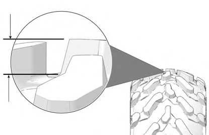 Always replace tires when tread depth is worn to 3 mm (1/8”) or less.
WHEEL REMOVAL

Do not service axle nuts that have a cotter pin installed. Your authorized dealer can assist.
WARNING
- Stop the engine, put the transmission in PARK (P), and lock the temporary brake lock.
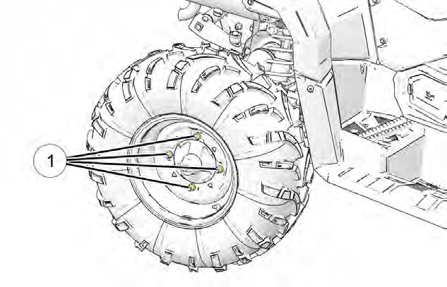
- Loosen the wheel nuts q slightly.

- Elevate the side of the vehicle by placing a suitable stand under the footrest frame.

Make sure the vehicle is properly lifted and supported prior to service.
WARNING
- Remove the wheel nuts and remove the wheel.
WHEEL INSTALLATION
- Stop the engine, put the vehicle in PARK (P), and set the temporary brake lock.
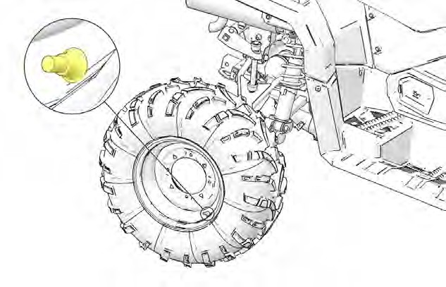 Place the wheel on the hub with the valve stem toward the outside and rotation arrows on the tire pointing toward forward rotation (if equipped).
- Install the wheel nuts q and finger-tighten them.
- Lower the vehicle to the ground.
- Torque the wheel nuts to specification.
WHEEL NUT TORQUE SPECIFICATIONS
Check the wheel nut torques occasionally and when they’ve been loosened for maintenance service.
Lug Nut (Aluminum Wheels) | Front and Rear | 30 ft-lbs (41 N·m)PLUS 70 degrees |
2-Piece Flange Nut (Steel Wheels)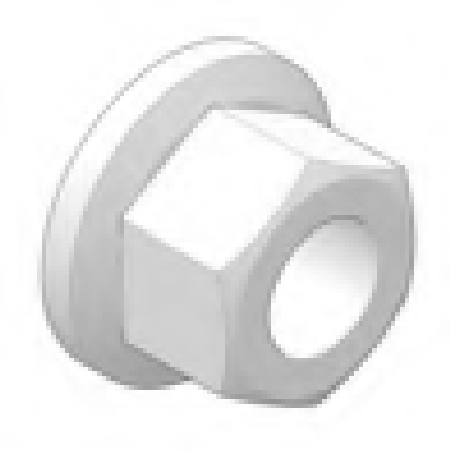 | Front and Rear | 27 ft-lbs (37 N·m) |
 TOE ALIGNMENT

Severe injury or death can result from improper toe alignment and adjustment. Do not attempt to adjust tie rod alignment. All tie rod adjustments should be performed by an authorized POLARIS dealer or other qualified service facility.
WARNING
Use the following procedure to check the toe alignment of the vehicle. The recommended toe alignment is 1/4-1/2 inch (6-12 mm).
- Position the vehicle on a level surface.
- Place the handlebars in a straight-ahead position.
- Tie a length of string between two stands. Position the stands so that the string is flush with the side of the rear tire. If available, you may use a long straight-edge instead of string.
- Measure the distance from the string to the rim at the front q and rear w of the front rim. The rear measurement should be 1/8–1/4 inch (3–6 mm) more than the front measurement on each side of the vehicle to obtain the recommended 1/4–1/2 inch (6–12 mm) toe out alignment.
- Repeat the measurement procedure on the other side of the vehicle.
- If you discover improper alignment, see your POLARIS dealer for service.
CAMBER AND CASTER
The camber and caster are non-adjustable.
AIR FILTER
It is recommended that the air filter is replaced annually. When riding in extremely dusty conditions, replacement is required more often.
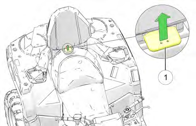
- Lift up on the rear of the seat.
- Pull the seat back and free of the tabs.
When reinstalling seat, make sure the slots in the seat engage the tabs in the fuel tank.
NOTICE
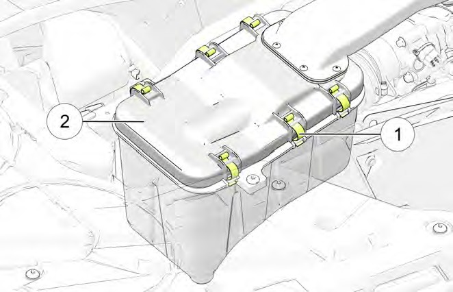
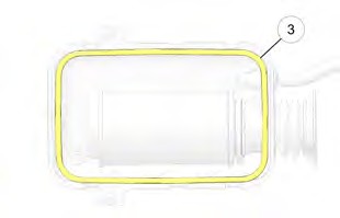 Remove the six clips q from air box cover and remove cover w.
- Inspect the gasket e. It should adhere tightly to the cover and seal all the way around.
 Loosen the air filter hose clamp r
and remove air filter assembly.
- Inspect the air filter and replace if necessary. If the filter has been soaked with fuel or oil, it must be replaced.
- Reinstall the air filter on the main filter mount. Place hose clamp over the assembly and torque to specification.
Apply a small amount of general purpose grease to the sealing edges of the filter before reinstalling.
NOTICE
Air Filter Hose Clamp:
20 in-lbs (2 N·m)
TORQUE
The air filter should rest on the filter supports. Proper placement of the air filter is important to prevent rattles and air leaks.
NOTICE
- Install air box cover and secure with the clips.
FUSE REPLACEMENT
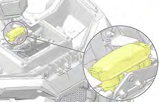 If the engine stops or will not start, or if you experience other electrical failures, a fuse may need replacement. Locate and correct any short circuits that may have caused the blown fuse, then replace the fuse. Spare fuses are provided in the tool kit.
To replace a fuse, do the following:
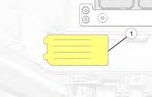
- Open the front box cover, and remove the access panel.
- Remove fuse box cover.
- Remove the suspect fuse from the fuse panel. If the fuse is blown, install a new fuse with the same amperage.
- Secure the fuse box cover and access panel.
- Secure the front box cover.
LIGHTS

Poor lighting can result in reduced visibility when driving. Headlight and taillight lenses become dirty during normal operation. Clean headlights frequently and replace burned out headlamps promptly.
Always make sure lights are adjusted properly for best visibility.
CAUTION
HEADLIGHT LAMP REPLACEMENT
When servicing a halogen lamp, don’t touch the lamp with bare fingers. Oil from your skin leaves a residue, causing a hot spot that will shorten the life of the lamp. If fingers do touch a lamp, clean it with denatured alcohol.

Hot components can cause burns to skin. Allow lamps to cool before servicing.
CAUTION
-
- Remove the seven (7) headlight pod screws. Pull the pod cover forward.
- Unplug the headlamp from the wiring harness. Be sure to pull on the connector, not on the wiring.
- Turn the lamp counter-clockwise to remove it.
- Apply dielectric grease to the socket and install the new lamp. Make sure the tab on the lamp locates properly in the housing.
- Reassemble the pod.
LED HEADLIGHT REPLACEMENT (IF EQUIPPED)
On models equipped with LED headlights, if the headlights become inoperable, the entire assembly must be replaced by your authorized Polaris dealer or other qualified service facility.
HIGH BEAM ADJUSTMENT
The headlight beam can be adjusted slightly upward or downward. Use the following procedure to make the adjustment.
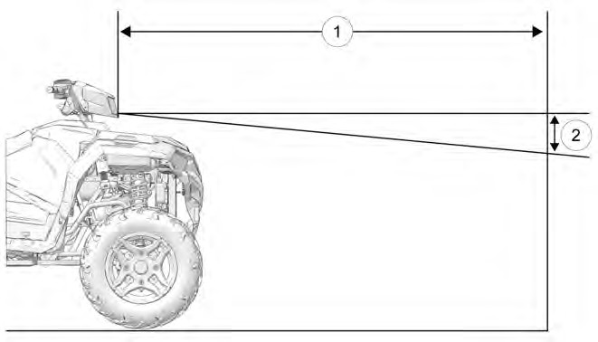
Image is for reference only. Your model might differ slightly.
NOTICE
- Position the vehicle on a level surface with the headlight approximately 25 ft (7.6 m) from a wall q. Place the transmission in PARK.
- Measure the distance from the floor to the center of the headlight and make a mark on the wall at the same height.
- Start the engine. Turn the headlight switch to high beam.
- Observe the headlight aim on the wall. The most intense part of the headlight beam should be 2 in (5 cm) below the mark on the wall w. Include rider weight on the seat when measuring.
- The adjustment screw is located on the right side of the headlight pod. To adjust the beam, loosen the screw. Adjust the headlamp to the desired position, then tighten the screw.
BUMPER LIGHT ADJUSTMENT
 The low beam can be adjusted slightly upward or downward. To adjust the bumper headlight, do the following:
-
- Loosen the Phillips® screw located at the rear of the headlamp.
- Tilt the headlamp upward or downward.
- Tighten the screw.
HEADLIGHT HOUSING REPLACEMENT
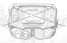 Remove the four headlight pod screws q and remove the front half of the pod from the vehicle.
- Remove each rubber o-ring retainer w on each side of the pod bracket and remove the headlight adjuster screw e.
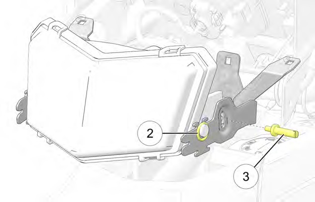
- Disconnect the main wiring harness from the back of the headlight.
- Lift the headlight out of the vehicle to remove it.
- Reverse steps for installation. Torque screws to specification.
Headlight Pod Screws:
10 in-lbs (2 N·m)
TORQUE
- Adjust the headlight pod.
LOWER HEADLAMP REPLACEMENT
- Turn the back of the headlight harness counter-clockwise and pull the harness assembly away from the headlight assembly.
- Remove the headlamp and install the new headlamp.
- Reinstall the harness assembly into the headlight assembly.
Take care to avoid touching the glass on the new headlight bulb. Fingerprints on the glass may result in premature failure.
NOTICE
- Turn the headlight harness clockwise to secure the headlamp.
TAILLIGHTS/BRAKE LIGHTS REPLACEMENT
The taillight assembly is not serviceable. If the light fails to operate properly, replace the entire taillight assembly.
SPARK PLUGS
SPARK PLUG RECOMMENDATIONS
Refer to the specifications section for the recommended spark plug type and gap for your vehicle. Torque spark plugs to specification.
Using non-recommended spark plugs can result in serious engine damage.
Always use POLARIS-recommended spark plugs or their equivalent.
NOTICE
| ENGINE | TORQUE SPECIFICATION |
| 570 | 9 ft-lbs (12 N·m) |
SPARK PLUG INSPECTION
Spark plug condition is indicative of engine operation. Check the spark plug for the correct color.

A hot exhaust system and engine can cause burns. Wear protective gloves when removing a spark plug for inspection. Allow engine to cool before removing spark plug wire.
CAUTION
- Rotate the spark plug cap 1/4 turn and pull it off the spark plug.
- Rotate the spark plug counter-clockwise to remove it.
- Reverse the procedure for spark plug installation. Torque to specification.
NORMAL PLUG
The normal insulator tip is gray, tan or light brown. There will be few combustion deposits. The electrodes are not burned or eroded. This indicates the proper type and heat range for the engine and the service.
The tip should not be white. A white insulator tip indicates overheating, caused by use of an improper spark plug or incorrect throttle body adjustments.
WET FOULED PLUG
The wet fouled insulator tip is black. A damp oil film covers the firing end. There may be a carbon layer over the entire nose. Generally, the electrodes are not worn. General causes of fouling are excessive oil consumption, use of
non-recommended oil, or poor fuel quality.
VEHICLE IMMERSION
If your vehicle becomes immersed, major engine damage can result if the machine is not thoroughly inspected. Take the vehicle in for service before starting the engine. Your POLARIS dealer can provide this service.
If it’s impossible to take your ATV to a dealer before starting it, follow the steps outlined below.
-
- Move the ATV to dry land or at the very least, to water below the footrests.
- Check the air box. If water is present, dry the air box and replace the filter with a new filter. If equipped, remove the air box drain plug to drain water. Reinstall the drain plug.

Serious damage could occur if the air box drain plug is not reinstalled properly.
CAUTION
-
- Remove the spark plug.
- Turn the engine over several times using the electric start.
- Dry the spark plugs. Reinstall the plugs or install new plug.
- Attempt to start the engine. If necessary, repeat the drying procedure.

Serious damage can occur after immersion if fluids are not changed promptly.
Your authorized dealer can assist.
CAUTION
-
- Take the vehicle in for service as soon as possible, whether you succeed in starting it or not. Your authorized dealer can provide the required service.
- If water has been ingested into the PVT, follow the procedure in the PVT System section for drying out the PVT.
SPARK ARRESTOR (TOURING MODELS)
SPARK ARRESTOR SERVICE
WARNING

Do not perform clean out immediately after the engine has been run, as the exhaust system becomes very hot. Serious burns could result from contact with exhaust components.
To reduce fire hazard, make sure that there are no combustible materials in the area when purging the spark arrestor.
Wear eye protection.
Do not stand behind or in front of the vehicle while purging the carbon from the spark arrestor.
Never run the engine in an enclosed area. Exhaust contains poisonous carbon monoxide gas.
Do not go under the machine while it is inclined. Put the transmission in PARK (P), lock the temporary brake lock, and block the wheels to prevent roll back.
Failure to heed these warnings could result in serious personal injury or death.
The exhaust pipe must be periodically purged of accumulated carbon as follows:
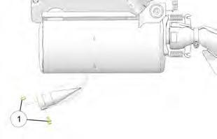
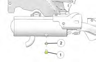 Remove the spark arrestor clean out bolt q and washer w located on the bottom of the muffler.
- Put the transmission in PARK (P) and start the engine. Purge the accumulated carbon from the system by momentarily revving the engine several times.
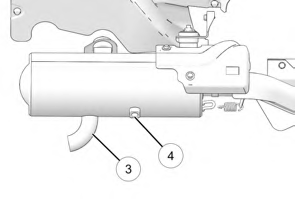 If some carbon is expelled, cover the exhaust outlet e and lightly tap on the pipe around the clean out weld nut r with a rubber mallet while revving the engine several more times.
- If particles are still suspected to be in the muffler, back the machine onto an incline so the rear of the machine is one foot higher than the front. Put the transmission in PARK (P), lock the temporary brake lock, and block the wheels to prevent roll back. Then repeat steps 2 and 3. SEE WARNING.
- If particles are still suspected to be in the muffler, drive the machine onto the incline so the front of the machine is one foot higher than the rear. Put the transmission in PARK (P), lock the temporary brake lock, and block the wheels to prevent roll back. Then repeat steps 2 and 3. SEE WARNING.
- Repeat steps 2 through 5 until no more particles are expelled when the engine is revved.
- Stop the engine and allow the arrestor to cool.
- Install the spark arrestor clean out bolt and washer. Torque bolt to specification.
Spark Arrestor Clean Out Bolt:
22 ft-lbs (30 N·m)
TORQUE
SPARK ARRESTOR (X2 / 6X6 MODELS)
SPARK ARRESTOR SERVICE
WARNING

Do not perform clean out immediately after the engine has been run, as the exhaust system becomes very hot. Serious burns could result from contact with exhaust components.
To reduce fire hazard, make sure that there are no combustible materials in the area when purging the spark arrestor.
Wear eye protection.
Do not stand behind or in front of the vehicle while purging the carbon from the spark arrestor.
Never run the engine in an enclosed area. Exhaust contains poisonous carbon monoxide gas.
Do not go under the machine while it is inclined. Put the transmission in PARK (P), lock the temporary brake lock, and block the wheels to prevent roll back.
Failure to heed these warnings could result in serious personal injury or death.
The spark arrestor should be periodically cleaned to remove accumulated carbon. A plugged spark arrestor will affect engine performance. Replace a cracked or damaged spark arrestor before running the vehicle.
 Remove the spark arrestor screen fasteners q.
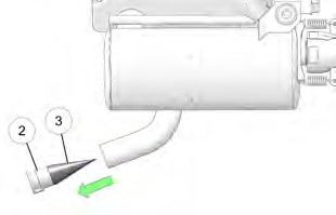 Remove the spark arrestor w from the end of the muffler.
- Use a non-synthetic brush to clean the screen e on the spark arrestor. If necessary, blow debris from the screen with compressed air.
- Inspect the screen for wear and damage. Replace if damaged.
- Install the spark arrestor. Torque fasteners to specification.
Spark Arrestor Screen Fasteners:
8 ft-lbs (11 N·m)
TORQUE
PVT SYSTEM
WARNING

Failure to comply with the instructions in this warning can result in severe injury or death.
Do not modify any component of the PVT system. Doing so may reduce its strength so that a failure may occur at a high speed. The PVT system has been precision balanced. Any modification will cause the system to be out of balance, creating vibration and additional loads on components.
The PVT system rotates at high speeds, creating large amounts of force on clutch components. Extensive engineering and testing has been conducted to ensure the safety of this product. However, as the owner, you have the following responsibilities to make sure this system remains safe:
-
- Always follow all recommended maintenance procedures. Always look for and remove debris inside and around the clutch and vent system when replacing the belt.
- See your POLARIS dealer, or other qualified person, for service and repair assistance.
- This PVT system is intended for use on POLARIS products only. Do not install it in any other product.
- Always make sure the PVT housing is securely in place during operation.
The basic operation of the POLARIS PVT system is dependent on engine speed and vehicle torque requirements. As engine speed increases, the force exerted on the movable drive sheave by the flyweights also increases. This, in turn, increases the amount of pinch applied to the drive belt. Similarly, if the engine speed decreases, the amount of centrifugal force decreases, reducing the amount of belt pinch.
On POLARIS ATVs, the approximate gear ratio difference between high and low range is 1:2.25. This difference in gearing affects the operation of the PVT, especially at speeds less than 7 MPH (11 km/h), due to the system’s dependence on engine speed.
For example, when operating at a ground speed of 3 MPH (5 km/h) in low range, the engine speed would be around 2700–3000 RPM. This is well above the engagement speed of 1500-1800 RPM. However, in high range at 3 MPH (5 km/h), the engine would be running at only 1500–1800 RPM. Whenever operating this close to the engagement speed, the engine may be running at a speed too low to provide the pinch needed to prevent belt slip. Belt slip is responsible for creating the excessive heat that destroys belts, wears clutch components and causes outer clutch covers to fail.
The air temperature in the clutch cover is substantially reduced by using low range while operating at low ground speeds. Reducing the temperature inside the clutch cover greatly extends the life of the PVT components (belt, cover, etc.).
WHEN TO USE LOW RANGE AND HIGH RANGE
| CONDITION | RANGE TO USE |
| Operating at speeds less than 7 MPH (11 km/h) | Low |
| Towing heavy loads | Low |
| Operating in rough terrain (swamps, mountains, etc.) | Low |
| Operating at speeds greater than 7 MPH (11 km/h) | High |
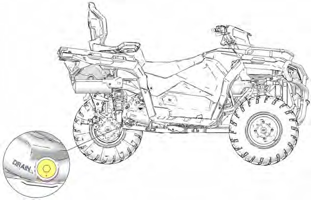
PVT DRYING
There may be some instances when water is accidently ingested into the PVT system. Use the following instructions to dry it out before operating.
- Position the vehicle on a level surface.
- Remove the drain plug. Allow the water to drain completely. Reinstall the drain plug.
- Start the engine. Place the transmission in PARK.
- Apply varying throttle for 10-15 seconds to expel the moisture and air-dry the belt and clutches. Do not hold the throttle wide open for more than 5 seconds.
- Allow the engine RPM to settle to idle speed, then shift the transmission to low range.
- Test for belt slippage. If the belt slips, repeat the process. Your vehicle requires service as soon as possible, which your authorized dealer can provide.
DRIVE BELT REMOVAL
- Position the vehicle on a level surface. Put the transmission in PARK (P) and lock the temporary brake lock.
- Elevate and safely support the rear of the vehicle.
- Remove the seat.
- Remove the left side panel / footwell. See page 163.
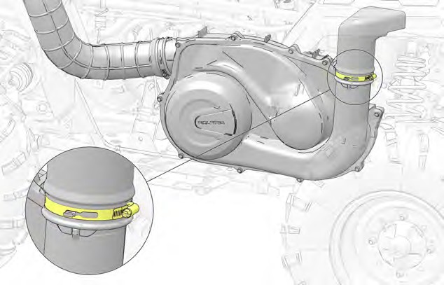 Loosen the PVT outlet duct clamp.
- Remove the 10 fasteners securing the outer PVT cover to the inner PVT cover.
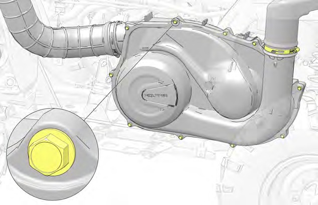
- Using care, pull the outer PVT cover out the side of the vehicle.
- Note the orientation of the drive belt so that it can be installed in the same direction.
- Insert the Belt Removal Tool q (included in your vehicle’s toolkit) into the threaded hole on the driven clutch as shown and turn clockwise to spread the clutch.
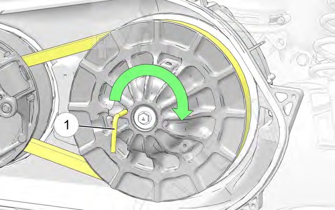
- Carefully walk the belt off the driven clutch and remove from the drive clutch.
DRIVE BELT INSPECTION
- Inspect belt for hour glassing (extreme circular wear in at least one spot and on both sides of the belt). Hour glassing occurs when the drive train does not move and the drive clutch engages the belt.
- Inspect belt for loose cords, missing cogs, cracks, abrasions, thin spots, or excessive wear. Compare belt measurements with a new drive belt. Replace if necessary.
- Belts with thin spots, burn marks, etc., should be replaced to eliminate noise, vibration, or erratic PVT operation. See General Diagnostic information for possible causes.
DRIVE BELT INSTALLATION
-
- Clean the inside of the PVT covers thoroughly.

Failure to remove all debris when replacing the belt could result in vehicle damage, loss of control, and severe injury or death.
WARNING
Orient the belt as it was removed or orient the new belt so that you can read the text.
IMPORTANT
-
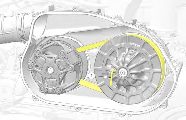
- With the Belt Removal Tool q installed, loop the belt over the drive clutch and over the driven clutch.
-
- Rotate the driven clutch and walk the belt into the clutch.
- Remove the Belt Removal Tool from driven clutch.
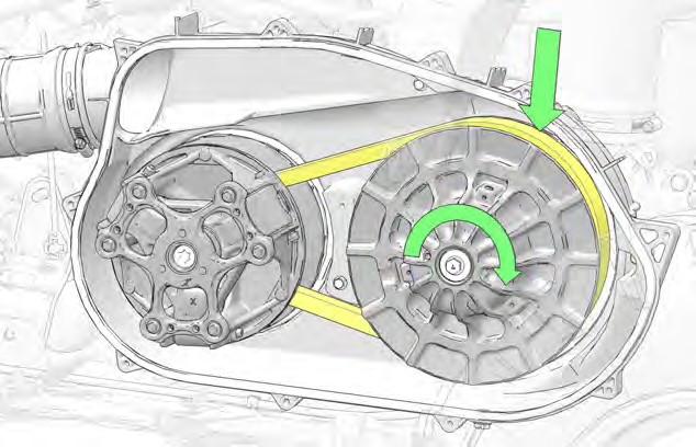 Rotate / spin the driven clutch and belt approximately 5-7 times clockwise to properly seat the belt into the driven clutch.
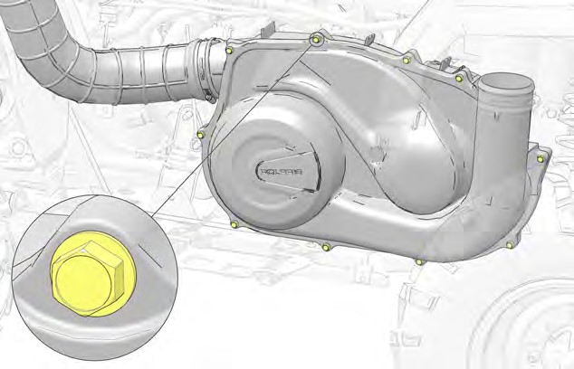 Install the outer PVT cover and 10 fasteners. Torque fasteners to specification.
Outer PVT Cover Fasteners:
44 in-lbs (5 N·m)
TORQUE
-
 Install the PVT outlet duct and clamp.
- Torque the PVT outlet duct clamp to specification.
Outlet Duct Clamp:
27 in-lbs (3 N·m)
TORQUE
-
- Install the left side panel / footwell. See page 166.
- Install the seat.
BATTERY

Improperly connecting or disconnecting battery cables can result in an explosion and cause serious injury, death, vehicle damage, and/or battery damage. When removing the battery, always disconnect the negative (-) black cable first. When reinstalling the battery, always connect the negative (-) black cable last.
WARNING
Always keep battery terminals and connections free of corrosion. If cleaning is necessary, remove corrosion with a stiff wire brush. Wash with a solution of one tablespoon baking soda and one cup water. Rinse well with tap water and dry off with clean shop towels. Coat the terminals with dielectric grease or petroleum jelly.
BATTERY REMOVAL

Improperly connecting or disconnecting battery cables can result in an explosion and cause serious injury, death, vehicle damage, and/or battery damage. When removing the battery, always disconnect the negative (-) black cable first. When reinstalling the battery, always connect the negative (-) black cable last.
WARNING
If electrolyte spills, immediately wash it off with a solution of one tablespoon baking soda and one cup water to prevent damage to the vehicle.
NOTICE
To remove the battery, do the following:
-
-
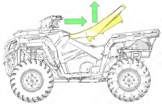
- Unlatch the front rack latches and open the front rack.
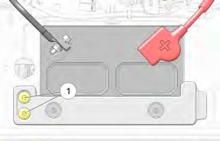
 Remove the two battery hold down strap screws q and remove strap from vehicle.
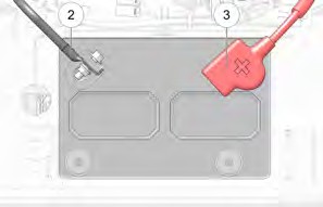
- Disconnect the negative (-) black cable w first. Then disconnect the positive (+) red cable e.
- Carefully lift the battery out of the vehicle.
-
BATTERY INSTALLATION

Improperly connecting or disconnecting battery cables can result in an explosion and cause serious injury, death, vehicle damage, and/or battery damage. When removing the battery, always disconnect the negative (-) black cable first. When reinstalling the battery, always connect the negative (-) black cable last.
WARNING
Using a new battery that has not been fully charged can damage the battery and result in a shorter life. It can also hinder vehicle performance. Refer to the battery charging information in the Maintenance chapter before installing the battery.
NOTICE

To reduce the chance of sparks when installing the battery, always connect the negative (-) black cable last.
CAUTION
- Clean battery cables and terminals with a stiff wire brush. Corrosion can be removed using a solution of one cup water and one tablespoon baking soda. Rinse well with clean water and dry thoroughly.
- Carefully install the battery into the vehicle.
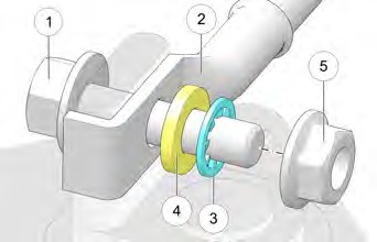 Connect the positive (+) red cable as shown below. Torque to specification.
q Flange Bolt
w Battery Cable
e Internal Tooth Lock Washer
r Flat Washer
t Flange Nut (Torque Applied)
Battery Terminals
62 in-lbs (7 N·m)
TORQUE
- Install positive battery boot.
- Connect and tighten the negative (-) black cable. Torque to specification.
- Verify the battery cables are properly routed.
BATTERY STORAGE
Whenever the vehicle is not used for a period of three months or more, remove the battery from the vehicle, ensure that it’s fully charged, and store it out of the sun in a cool, dry place. Check battery voltage each month during storage and recharge as needed to maintain a full charge.
Image is for reference only. Your model might differ slightly.
NOTICE
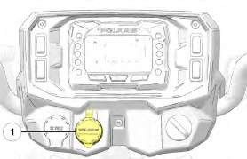
POLARIS recommends maintaining battery charge by using a POLARIS battery trickle charger or by charging once a month using the battery charge port q.
The POLARIS offered battery trickle charger can be left connected during the
storage period, and will automatically charge the battery if the voltage drops below a pre-determined point. See the POLARIS Products chapter for the part number.
POLARIS recommends using a trickle charger that shuts off automatically when the battery is fully charged. If you are not using a trickle charger that automatically shuts when the battery is fully charged, make sure to monitor the battery charge level and disconnect the charger when the battery is fully charged.
IMPORTANT

When using a battery trickle charger, always place the charger on the ground, or on a suitable elevated surface. Never place the charger on the vehicle or let it hang from the battery charge port while plugged in.
CAUTION
BATTERY CHARGING
Read all instructions before proceeding with the installation of this battery.
The battery is already filled with electrolyte and has been fully charged at the factory. Never pry the caps off or add any other fluid to this battery.
The single most important thing about maintaining the battery is to keep it fully charged. Use a voltmeter to measure DC voltage to determine the battery state of charge.

An overheated battery may explode, causing severe injury or death. Always watch charging times carefully. Stop charging if the battery becomes very warm to the touch. Allow it to cool before resuming charging.
WARNING
For a refresh charge, follow all instructions carefully.
- The battery should be disconnected from a load or charger for at least two hours before checking voltage. Check the battery voltage with a voltmeter. A fully charged battery will register 12.6 V or higher.
- If the voltage is less than 12.6 volts, recharge the battery at 2 amps or less until the battery charger indicates charge complete.
- When using an automatic charger, refer to the charger manufacturer’s instructions for recharging. When using a constant current charger, use the following guidelines via the table below.
VOLTAGE TABLE
Always verify battery condition before and 1-2 hours after the end of charging.
| STATE OF CHARGE | VOLTAGE | ACTION | CHARGE TIME (USING CONSTANT CURRENT CHARGER @STANDARD AMPS SPECIFIED ON TOP OF BATTERY) |
| 100% | 12.6-12.8 volts | Low Maintenance Battery: check after 60 days | None required |
| 50%-75% | 12.0-12.5 volts | Needs charge | 5-11 hours |
| 25%-50% | 11.5-12.0 volts | Needs charge | At least 13 hours, verify state of charge |
| 0%-25% | 11.5 volts or less | Needs charge | At least 20 hours |
BATTERY IDENTIFICATION
It is important to identify the type of battery installed in the vehicle. Different types of batteries require different service procedures. Proper servicing and upkeep of the battery is very important for maintaining long battery life. All Polaris ORV models include either a Conventional battery or a Low Maintenance battery.
IMPORTANT
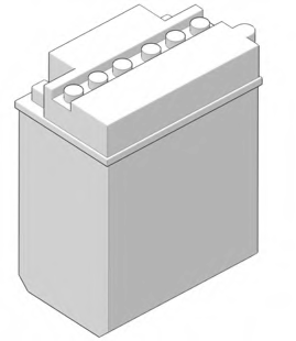 CONVENTIONAL BATTERY
-
- The battery is NOT activated when packaged
- Distilled water and electrolyte added as required
- Removable cap plugs located on top of battery
- Vent tube located on side of battery
LOW MAINTENANCE BATTERY
-
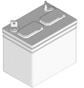 Battery activated when packaged
- Distilled water and electrolyte NEVER added
- Non removable cap(s) located on top of battery
LOW MAINTENANCE BATTERY BEST PRACTICES
Some Polaris ORV models include either a Lead Acid or Absorbed Glass Mat (AGM) Low Maintenance battery. See the Service Manual for procedures on how to charge, maintain, and test a Lead Acid or AGM Low Maintenance battery.
Using a new battery that has not been fully charged can damage the battery and result in a shorter life. It can also hinder vehicle performance.
NOTICE
LEAD ACID LOW MAINTENANCE BATTERY
CHARGING
- The battery must be fully charged before use or battery life will be significantly reduced by 10-30% of the battery’s full potential.
- Nominal voltage is 12.6 to 12.8 Volts when fully charged. If the voltage falls below 12.5V, charge it immediately, or the battery service life and vehicle performance may be affected.
- Polaris recommends using a BatteryMINDer® 12V 1.5 AMP (PN 2830404) charger (or a similar charger), which can be ordered through your normal parts channel.
- Charge the battery with a charging output no larger than 10% of the battery’s amp-hour rating.
MAINTENANCE
- Recharge the battery to its full capacity every 30 to 60 days.
- If the battery is stored or used in a partially charged condition, hard crystal sulfation will form on the plates, reducing the efficiency and service life of the battery.
- Never add electrolyte or distilled water to the battery. Doing so will damage the case and shorten the life of the battery.
- Store the battery in the vehicle with the cables disconnected, or store the battery in a cool / dry location. Batteries will self discharge more rapidly when stored in extreme temperatures.
LOW MAINTENANCE BATTERIES
CHARGING
-
- Polaris recommends using a BatteryMINDer® 1.5 AMP (PN 2830404) charger, which can be ordered through your normal parts channel.
- Nominal voltage is 12.6–12.8 Volts when fully charged. If the voltage falls below 12.5V, charge it immediately, or the battery runs the risk of sulfation.
MAINTENANCE
-
- Never add electrolyte or distilled water to the battery. Doing so will damage the case and shorten the life of the battery.
- If you do not drive the vehicle for more than TWO weeks, maintain the battery with the BatteryMINDer® 1.5 AMP (PN 2830404) charger.
- If you plan to store the vehicle for ONE month or longer, remove the battery from the vehicle and store the battery in a cool / dry location. Continue to maintain the battery with the BatteryMINDer® 1.5 AMP (PN 2830404) charger and inspect the battery every 60 days.
SUSPENSION SPRING PRELOAD ADJUSTMENT
The rear shock absorber springs are adjustable on all models. The front shock absorber springs are only adjustable on dual a-arm suspension models.
NOTICE
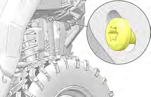
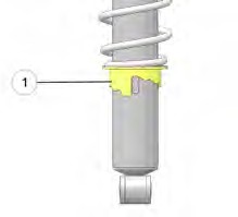 Rotate the adjuster cam q either direction to increase or decrease spring tension. Always adjust both the left and right sides equally.
Vehicle loads affect suspension spring pre-load requirements. Use the Shock Spanner Wrench included in the vehicle’s tool kit to adjust pre-load as necessary to avoid bottoming of the shocks.
Shock Spanner Wrench
2871095
HANDLEBARS
The handlebars can be adjusted for rider preference.

Improper adjustment of the handlebars or incorrect torquing of the adjuster block tightening bolts can cause limited steering or loosening of the handlebars, resulting in loss of control and serious injury or death. Follow the adjustment procedures exactly, or see your POLARIS dealer for service.
WARNING
- Remove the upper headlight pod.
- Loosen the four handlebar bolts.
- Adjust the handlebar to the desired height. Be sure the handlebars do not contact the gas tank or any other part of the machine when turned fully to the left or right.
- Torque the front two bolts to specification, then torque the rear two bolts. A gap of up to 1/8″ (3 mm) will remain at the rear of the clamp blocks.
Handlebar Bolts:
14 ft-lbs (19 N·m)
TORQUE
- Reinstall the headlight pod.
CLEANING AND STORAGE
WASHING THE VEHICLE
Keeping your POLARIS vehicle clean will not only improve its appearance but it can also extend the life of various components.
Water in the PVT system could cause the drive belt to become wet and slip in the clutches. Always avoid spraying water directly toward any intake pre-filters. If water does enter the PVT intake, follow the procedure in the PVT Drying section.
Certain products, including insect repellents and chemicals, will damage plastic surfaces. Do not allow these types of products to contact the vehicle.
The best way to clean your POLARIS vehicle is with a garden hose and a pail of mild soap and water.
-
- Use a professional-type washing cloth, cleaning the upper body first and the lower parts last.
- Rinse with clean water frequently.
- Dry surfaces with a chamois to prevent water spots.
WASHING TIPS
-
-
- Avoid the use of harsh cleaners, which can damage the finish.
- Do not use medium to heavy duty compounds on the finish.
- Always use clean cloths and pads for cleaning and polishing. Old or reused cloths and pads may contain dirt particles that will scratch the finish.
- Do not use high-speed polishers/buffers on body panels, as damage or color fading may occur.
-
USING A HIGH PRESSURE WATER SYSTEM

Spilled oil left on engine components or in the engine area may pose a fire hazard. Use shop rags to clean any spilled oil. If needed, use a non-flammable solvent on the rag to aid in the cleaning process. Do not use any device such as pressurized water or air as this may disperse the oil onto the engine components and could pose a fire hazard.
WARNING
If a high pressure water system is used for cleaning, exercise extreme caution. The maximum pressure should not exceed 3000 psi (20684.27 kPa), 2.5 GPM (567.81 LPH) with a 40° pressure washer nozzle. Make sure to keep the pressure washer nozzle 2 ft (60 cm) from the vehicle and away from the surface being cleaned. High water pressure could remove paint and labels and damage radiator fins and/or impair a radiator’s effectiveness. High water pressure with a hot temperature could also damage brake lines with the nozzle at a close proximity even with a short exposure time. Avoid directing the water stream at the following items:
- Wheel bearings
- Radiator
- Transmission seals
- Brakes / brake lines
- Body panels
- Labels and decals
- Electrical components and wiring
- Air intake components
- Throttle and shift cables and controls
- Seats
If warning and safety labels are damaged, contact your POLARIS dealer for free replacement.
Grease all zerk fittings immediately after washing. Allow the engine to run for a while to evaporate any water that may have entered the engine or exhaust system.
POLISHING THE VEHICLE
POLARIS recommends the use of common household aerosol furniture polish for polishing the finish on your POLARIS vehicle. Follow the instructions on the container.
POLISHING TIPS
- Avoid the use of automotive products, some of which can scratch the finish of your vehicle.
- Always use clean cloths and pads for cleaning and polishing. Old or reused cloths and pads may contain dirt particles that will scratch the finish.
STORAGE TIPS
Starting the engine during the storage period will disturb the protective film created by fogging and damage could occur. Never start the engine during the storage period.
NOTICE
CLEAN THE EXTERIOR
Make any necessary repairs and clean the vehicle as recommended. See the Washing the Vehicle section.
STABILIZE THE FUEL
- Fill the fuel tank.
- Add POLARIS Carbon Clean Fuel Treatment or POLARIS Fuel Stabilizer or equivalent fuel treatments or stabilizers. Follow the instructions on the container for the recommended amount. Carbon Clean removes water from fuel systems, stabilizes fuel and removes carbon deposits from pistons, rings, valves and exhaust systems.
- Allow the engine to run for 15-20 minutes to allow the stabilizer to disperse through the entire fuel delivery system.
OIL AND FILTER
Change the oil and filter. See the Engine Oil section.
AIR FILTER / AIR BOX
Replace the air filter. See Maintenance Chapter. Clean the air box.
FLUID LEVELS
Inspect the fluid levels. Add or change fluids as recommended in the Polaris Maintenance Schedule.
- Demand drive fluid (front gearcase)
- Rear gearcase fluid (if equipped)
- Transmission fluid
- Brake fluid (change every two years and any time the fluid looks dark or contaminated)
- Coolant (test strength/fill)
INSPECT AND LUBRICATE
Inspect all cables and lubricate all areas of the vehicle as recommended in the Polaris Maintenance Schedule.
FOG THE ENGINE
- Treat the fuel system with POLARIS Carbon Clean or other equivalent fuel treatment. Follow the instructions on the container. Start the engine. Allow it to idle for several minutes so the Carbon Clean reaches the injectors. Stop the engine.
- Remove the spark plug and add 1–1.5 oz. (29.5–44 cc.) of engine oil. To access the plug hole, use a section of clear 6 mm (1/4”) hose and a small plastic squeeze bottle filled with the pre-measured amount of oil. Do this carefully! If you miss the plug holes, oil will drain from the spark plug cavities into the hole at the front of the cylinder head, and appear to be an oil leak.
- Reinstall the spark plug. Torque to specification.
- Apply dielectric grease to the inside of the spark plug cap. Do not reinstall the cap onto the plug at this step.
- Turn the engine over several times. Oil will be forced in and around the piston rings and ring lands, coating the cylinder with a protective film of fresh oil.
- Reinstall the spark plug cap.
- If POLARIS fuel system additive is not used, fuel tank, fuel lines, and injectors should be completely drained of gasoline.
BATTERY MAINTENANCE
See the Battery Storage and Battery Charging sections for storage and charging procedures.
STORAGE AREA / COVERS
Be sure the storage area is well ventilated. Cover the vehicle with a genuine POLARIS cover. Do not use plastic or coated materials. They do not allow enough ventilation to prevent condensation, and may promote corrosion and oxidation.
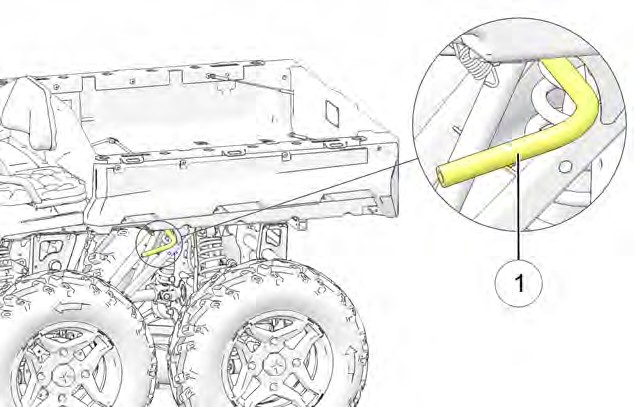
 TRAILERING YOUR VEHICLE
Follow these procedures when transporting the vehicle.
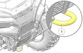
-
- Stop the engine.
- Place the transmission in PARK.
- Secure the fuel cap, oil cap, and seat.
- Remove the key to prevent loss during transporting.
- Use suitable straps or rope to secure the vehicle to the front tow hook q and rear tow bracket w. Do not attach tie straps to the front A-arm bolt pockets, racks, or handlebars.