FEATURES AND CONTROLS
OVERVIEW
Image is for reference only. Your model might differ slightly.
NOTICE
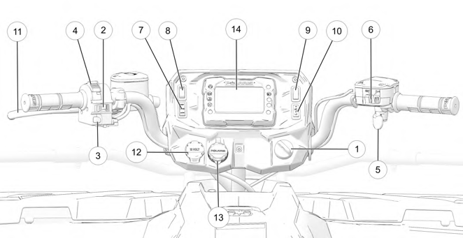
q Ignition Switch
w Engine Stop Switch
e Mode / Reverse Override Switch
r Headlight Switch
t Throttle Lever
y Driveline Switch / AWD Momentary Switch
u Drive Mode Switch (if equipped)
i Auxiliary Switch (if equipped)
o Hand Warmer Switch (if equipped) a Thumb Warmer Switch (if equipped) s Brake Lever
d Auxiliary Outlet
f Battery Charge Port
g Digital Display
IGNITION SWITCH
Use the ignition switch q to start the engine. The key can be removed from the switch when it is in the OFF position.
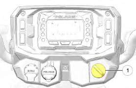
Image is for reference only. Your model might differ slightly.
NOTICE
|
SWITCH POSITION |
FUNCTION |
|
OFF |
Turn the key to the OFF position to stop the engine. Electrical circuits are off. |
|
RUN |
Turn the key the RUN position to activate electrical components. Electrical circuits are on. Electrical equipment can be used. |
|
START |
Turn the key to the START position to engage the electric starter. See the Starting the Engine section for starting procedures. |
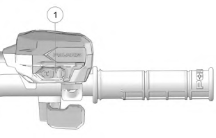
LEFT-HAND CONTROLS
ENGINE STOP SWITCH
![]()
Move the engine stop switch q to the OFF position to stop the engine quickly.
Move the engine stop switch to the RUN position before attempting to start the engine. The engine will not start or run when the switch is off. Both the main switch and the engine stop switch will shut off all electrical power to the vehicle, including the lights.
MODE / REVERSE OVERRIDE SWITCH
Pressing the override button while the throttle is open can cause loss of control, which may result in serious injury or death. Always release the throttle before pressing the override button.
WARNING
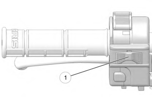
 This vehicle is equipped with a reverse speed limiter system. To gain additional wheel speed while backing, release the throttle and press the override button w. The reverse override button also acts as a MODE button for the digital display when held down for approximately one half second. The override button will not function as a MODE button if the transmission is in reverse.
HEADLIGHT SWITCH
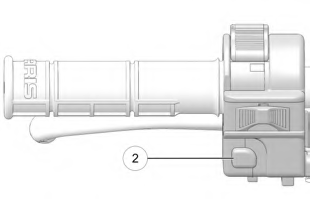
 Use the headlight switch e to turn the lights on and off and to change the lights from high beam to low beam. The key must be in the ON position and the engine stop switch must be in the RUN position.
RIGHT-HAND CONTROLS
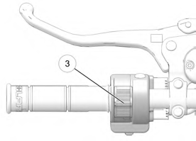
THROTTLE LEVER
![]()
Operating an ATV with sticking or improperly operating throttle controls could cause an accident. Never start or operate an ATV that has a sticking or improperly operating throttle. Immediately contact your POLARIS dealer or other qualified person for service if throttle problems arise.
Failure to check or maintain proper operation of the throttle system can result in an accident if the throttle lever sticks during operation. Always check the lever for free movement and return before starting the engine. Also check occasionally during operation.
Modifications to the electronic throttle control could result in failure to perform as designed, which could result in an accident. Do not attempt to modify the throttle control system or replace it with any after market throttle mechanisms.
WARNING
 Engine speed and vehicle movement are controlled by pressing the throttle lever q. The throttle lever is spring loaded. Engine speed returns to idle when the lever is released. This ATV is equipped with a throttle release switch, which is designed to reduce the risk of a frozen or stuck throttle.
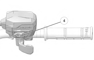
DRIVELINE SWITCH (IF EQUIPPED)
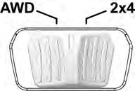
 The All Wheel Drive (AWD) system is controlled by the Driveline Switch w. Use this switch to engage AWD or 2×4. The vehicle automatically engages AWD when operating in forward or reverse if the switch is set to AWD. For more information, see page 41.
DRIVELINE SWITCH (ADC MODELS) (IF EQUIPPED)
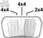
 The All Wheel Drive (AWD) system is controlled by the Driveline Switch e. Use this switch to engage ADC, 4×4, or 2×4. The vehicle automatically engages AWD when operating in forward or reverse if the switch is set to 4×4. For more information, see page 41.
AWD MOMENTARY SWITCH (ULTIMATE, X2, AND 6X6 MODELS)
 The All Wheel Drive (AWD) system is controlled by the AWD Momentary Switch r. Use this switch to engage TURF mode (if equipped), 2×4, AWD, or ADC. The vehicle automatically engages AWD when operating in forward or reverse if the switch is set to AWD. For more information, see page 43.
DRIVE MODE SWITCH (IF EQUIPPED)
The Drive Mode Switch has three positions:
 Performance (PERF)
- Standard (STND)
- Work (WORK)
Always use low gear for any of the following conditions regardless of the selected throttle control setting.
- Operating in rough terrain or over obstacles.
- Loading the vehicle onto a trailer.
- Towing heavy loads.
- Driving frequently at low RPM or at ground speeds below 7 MPH (11 km/h).
PERFORMANCE MODE
Offers a more aggressive feel to the power of the vehicle. Vehicle will accelerate harder with less throttle movement.
WORK MODE
Throttle is smoother than standard mode. Best for when the operator wants more precision over vehicle acceleration. This drive mode is recommended to be used when backing up with a trailer, driving over rough terrain, or loading vehicle on a trailer.
STANDARD MODE
Use for majority of driving.
 ALL WHEEL DRIVE SYSTEM
Switching to AWD or ADC mode (if equipped) while the rear wheels are spinning may cause severe drive shaft and gearcase damage. Always switch to AWD or ADC mode (if equipped) while the rear wheels have traction or are at rest.
NOTICE
The All Wheel Drive (AWD) system is controlled by the Driveline Switch. Engage AWD before getting into conditions where front wheel drive may be needed. If the rear wheels are spinning, release the throttle before switching to AWD.
AWD Models ADC Models
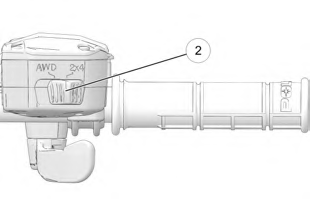
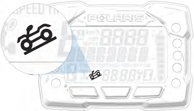
AWD MODE
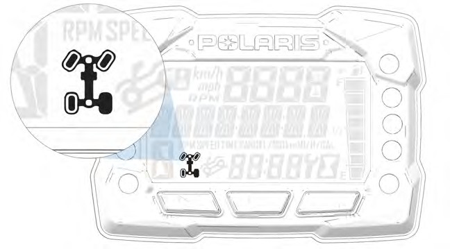
![]() When the driveline switch is set to 4×4 or AWD, the ATV is in four-wheel drive, and the AWD indicator icon is visible on the digital display.
When the driveline switch is set to 4×4 or AWD, the ATV is in four-wheel drive, and the AWD indicator icon is visible on the digital display.
When in AWD, the demand drive unit will automatically engage any time the rear wheels lose traction. When the rear wheels regain traction, the demand drive unit will automatically disengage. There is no limit to the length of time the vehicle may remain in AWD. The vehicle automatically engages AWD when operating in forward or reverse if the switch is set to 4×4 or AWD.
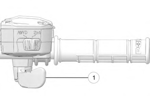
2X4 MODE
![]() When the driveline switch is set to 2×4, the ATV is in two-wheel drive at all times.
When the driveline switch is set to 2×4, the ATV is in two-wheel drive at all times.
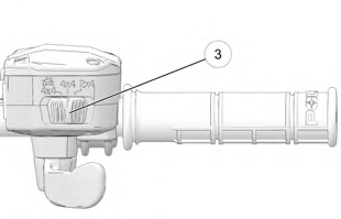
ADC MODE (IF EQUIPPED)
![]() When the driveline switch is set to ADC, the ADC system allows engine braking to all four wheels when the vehicle descends a hill or incline. Always move the 4×4 switch to ADC before ascending or descending a hill.
When the driveline switch is set to ADC, the ADC system allows engine braking to all four wheels when the vehicle descends a hill or incline. Always move the 4×4 switch to ADC before ascending or descending a hill.
ENGAGING AWD
The 4×4 or AWD switch may be turned on or off while the vehicle is moving. Initially, the vehicle’s electronic system will not enable AWD until the engine RPM is below 2800. Once enabled, AWD remains enabled until the 4×4 or AWD switch is turned off. If the switch is turned off while the demand drive unit is moving, it will not disengage until the rear wheels regain traction.
Engage the 4×4 or AWD switch before getting into conditions where front wheel drive may be needed. If the rear wheels are spinning, release the throttle before switching to AWD.
ALL WHEEL DRIVE SYSTEM
Available on Ultimate, X2, and 6×6 Models
 The All Wheel Drive (AWD) system is controlled by the AWD Momentary Switch q.
Engage AWD before getting into conditions where front wheel drive may be needed. If the rear wheels are spinning, release the throttle before switching to AWD mode.
- To engage TURF mode (X2 models), push the momentary switch to the left twice.
- To engage 2×4 mode, push the momentary switch to the left.
- To engage AWD mode, push the momentary switch to the right.
- To engage ADC mode, push the momentary switch to the right twice.
Switching to AWD or ADC mode while the rear wheels are spinning may cause severe drive shaft and gearcase damage. Always switch to AWD or ADC mode while the rear wheels have traction or are at rest.
NOTICE
TURF MODE (X2 MODELS)
![]()
Operating in TURF mode when on sloped, uneven, or loose terrain could cause loss of control and result in serious injury or death. One rear wheel may slip and lose traction or may lift up and grab when it touches the ground again.
WARNING
Operating in Turf Mode will unlock the rear differential and enable the rear wheels to rotate at different speeds. This function helps to decrease damage to turf surfaces.
To engage TURF mode, push the momentary switch to the left twice. When operating in TURF mode, the inside rear wheel will rotate independently from the outside wheel during turns. Operate in TURF mode only as needed to protect smooth, level surfaces from tire damage. DO NOT operate in TURF mode when climbing or descending hills, when sidehilling, or when operating on uneven, loose, or slippery terrain such as sand, gravel, ice, snow, obstacles, and water crossings. Always operate in AWD or ADC on these types of terrain.
2X4 MODE
To engage 2×4 mode, push the momentary switch to the left. AWD will disengage when engine speed slows to below 2800 RPM. The gauge will display “2×4.”
AWD MODE
To engage AWD mode, push the momentary switch to the right. AWD will engage when engine speed slows to below 2800 RPM. The gauge will display “AWD.” There is no limit to the length of time the vehicle may remain in AWD. The vehicle automatically engages AWD when operating in forward or reverse if the momentary switch is set to the AWD mode. Once enabled, AWD remains enabled until the AWD mode is turned off. If the AWD mode is turned off while the demand drive unit is moving, it will not disengage until the rear wheels regain traction. When in AWD, the demand drive unit will automatically engage any time the rear wheels lose traction. When the rear wheels regain traction, the demand drive unit will automatically disengage.
ADC MODE
To engage ADC mode, push the momentary switch to the right twice. When the switch is on ADC, the ADC system allows engine braking to all four wheels when the vehicle descends a hill or incline. Always engage ADC mode before ascending or descending a hill.
ACTIVE DESCENT CONTROL (ADC) SYSTEM (IF EQUIPPED)
 The ADC system allows engine braking to all four wheels when the vehicle descends a hill or incline. Always move the 4×4 or AWD switch to ADC before ascending or descending a hill.
ENGAGING ACTIVE DESCENT CONTROL
The ADC system will automatically engage when all four of the following conditions occur:
- The 4×4 or AWD switch must be in the ADC position
- Vehicle speed must be 15 mph (25 km/h) or less
- The throttle must be closed (throttle lever released)
- The transmission must be in gear (high, low or reverse)
DISENGAGING ACTIVE DESCENT CONTROL
The ADC system will automatically disengage if at least one of the following conditions occur:
- The 4×4 or AWD switch is moved out of the ADC position
- Vehicle speed exceeds 15 mph (25 km/h)
- The throttle is open (throttle is applied)
- The transmission is shifted to neutral or park
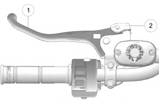
BRAKE SYSTEM
BRAKE LEVER
![]()
Operating the ATV with a spongy brake lever can result in loss of braking, which could cause an accident. Never operate the ATV with a spongy-feeling brake lever. Always contact your dealer for service before operating the vehicle.
WARNING
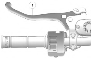 Squeeze the brake lever q toward the handlebar to apply the front and rear brakes. These brakes are hydraulically activated disc type brakes that are activated by only one lever. Always test brake lever travel and master cylinder fluid level before riding. When squeezed, the lever should feel firm.
Any sponginess would indicate a possible fluid leak or low master cylinder fluid level, which must be corrected before riding. Contact your POLARIS dealer or other qualified service facility for proper diagnosis and repairs.
MASTER CYLINDER/BRAKE FLUID
![]()
An over-full master cylinder may cause brake drag or brake lock-up, which could result in an accident. Maintain brake fluid at the recommended level. Do not overfill.
WARNING
Check the brake fluid in the master cylinder before each ride.
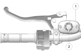 Position the ATV on a level surface.
- Position the handlebars so the master cylinder q is level.
- View the brake fluid level through the indicator window w on the top of the master cylinder. The eye will appear dark when the fluid level is full. When fluid is low, the eye will be clear.
- If the fluid level is low, remove the cover screws and add fluid to the fill line.
Do not overfill. Use DOT 4 brake fluid only.
- Reinstall the cover. Torque screws to 7 in-lbs (1 N·m).
![]()
Never store or use a partial bottle of brake fluid. Brake fluid is hygroscopic, meaning it rapidly absorbs moisture from the air. The moisture causes the boiling temperature of the brake fluid to drop, which can lead to early brake fade and the possibility of brake failure, which could result in an accident. After opening a bottle of brake fluid, always discard any unused portion.
WARNING
TEMPORARY BRAKE LOCK
![]()
Operating the ATV while the temporary brake lock is engaged could result in an accident or fire. Always make sure the lock is disengaged before operating.
WARNING
To engage the temporary brake lock, do the following:
 Place the transmission in PARK.
- Squeeze and release the brake lever q two or three times, then squeeze and hold.
- Push the temporary brake lock w
forward to engage the lock.
- Release the brake lever.
- To release the temporary brake lock, squeeze and release the brake lever. It will return to its unlocked position.
![]()
The temporary brake lock may relax if left on for a long period of time. Always block the wheels to prevent rolling. Always block the wheels on the downhill side of the ATV if leaving it parked on a hill. Another option is to park the ATV in a sidehill position. Never depend on the temporary brake lock alone if the ATV is parked on a hill.
WARNING
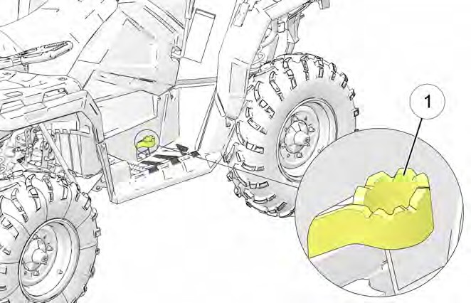 AUXILIARY FOOT BRAKE
![]()
Never back down a hill. Applying the auxiliary brake when backing down a hill may cause rear tipover, which could result in serious injury or death.
Use caution when applying the auxiliary brake. Do not aggressively apply the auxiliary brake when going forward. The rear wheels may skid and slide sideways, causing loss of control and serious injury or death.
WARNING
Image is for reference only. Your model might differ slightly.
NOTICE
The auxiliary brake system is intended to be used as a backup for the main brake system. Should the main system fail, use the auxiliary foot brake q.
The auxiliary foot brake is located on the inside of the right footrest. Operate this brake with your right foot. If the rear wheels slide while using the auxiliary brake, reduce brake pedal pressure to brake the rear wheels without skidding.
Check the brake fluid level frequently for the auxiliary brake system. The reservoir is located on the frame and can be accessed through the front right wheel well.
Maintain the fluid level between the maximum and minimum marks. Use DOT 4 brake fluid only.
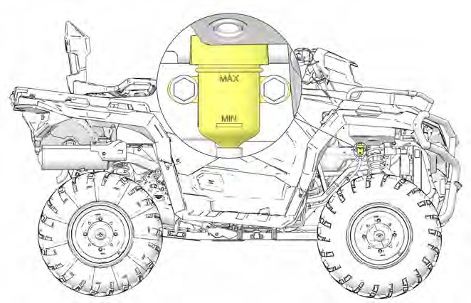
Image is for reference only. Your model might differ slightly.
NOTICE
 AUTOMATIC TRANSMISSION GEAR SELECTOR
The transmission gear selector is located on the right side of the vehicle.
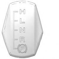 H: High Gear L: Low Gear N: Neutral R: Reverse P: Park
To shift gears, brake to a complete stop. When the engine is idling, move the lever to the desired gear.
Shifting gears with the engine speed above idle or while the vehicle is moving could cause transmission damage.
NOTICE
Whenever the ATV is left unattended, always place the transmission in PARK.
To extend belt life, use low forward gear when pulling a heavy load and when operating uphill at a slow speed.
NOTICE
PASSENGER SEAT (X2 MODELS)
Always make sure the passenger seat lock-out is functioning properly before operating with a passenger.
Do not operate the vehicle with the seat in the 2-up position when operating without a passenger. Always return the seat to the 1-up position for single-rider operation.
Never carry cargo in the rear box when operating the ATV in the 2-up mode with a passenger.
SEAT CONVERSION (X2 MODELS)
The rear seat can be adjusted to three different positions.
NOTICE
- Make sure the cargo box is securely latched.
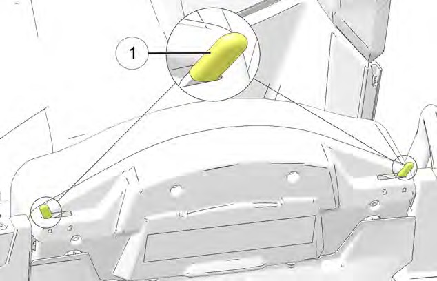 Slide the seat latch levers q inward to release the locks.
- Tilt the backrest slightly forward.
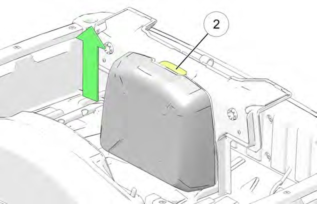
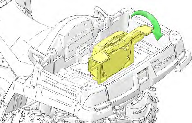 Pull the passenger backrest upward from the bed of the cargo box.
- Lift the adjustment latch w at the top of the passenger backrest. Raise the backrest to the desired position. Release the latch, making sure it locks into one of the three operating positions.
The backrest must be moved out of the lowest position before it can be secured in the upright position. The lowest position is for seat storage only. Do not leave the backrest in the lowest position. Always adjust the backrest to one of the three operating positions.
TIP
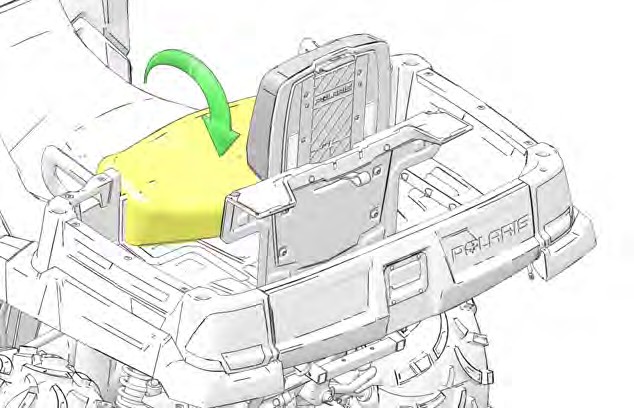 Lower the operator backrest to create the passenger seat. Two retaining pins under the seat should fit into the two grommets on the seat base.
- Test the passenger seat lockout by attempting to release the cargo box dump latch. If the dump latch releases, the seat is not secure. Repeat the set-up procedure. If the lock-out is not working properly, do not allow a passenger to ride the vehicle. See your POLARIS dealer for service.
- To return the vehicle to single-rider operation, reverse all steps. Always lower the passenger backrest to the lowest position before folding it down into the cargo box. Slide the seat latch levers outward to secure the locks.
INSTRUMENT CLUSTER
Features vary by model.
Refer to the Ride Command chapter for more information about the Ride Command display.
NOTICE
Your vehicle is equipped with one of four available gauge variants, (1) a standard gauge (no Bluetooth® functionality), (2) a Bluetooth®-equipped gauge,
(3) a no-button gauge, or (4) a 7” Ride Command display. If your gauge is equipped with Bluetooth®, the Bluetooth® icon will briefly display in the upper right corner of the gauge at start-up. If your model is equipped with a no-button gauge, use the MODE button on the left hand control to navigate the display menu.
The use of a high pressure washer may damage the instrument cluster. Wash the vehicle by hand or with a garden hose using mild soap. Do not use alcohol to clean the instrument cluster. Do not allow insect sprays to contact the lens. Immediately clean off any gasoline that splashes on the instrument cluster.
NOTICE
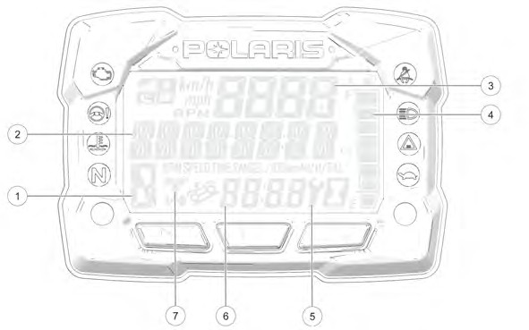
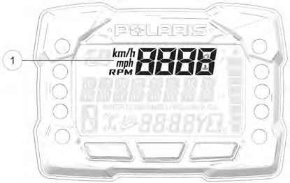
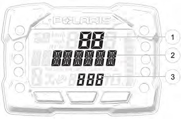
|
DISPLAY AREA |
FUNCTION |
|
q Gear Indicator |
H = High Gear L = Low Gear N = Neutral R = Reverse Gear P = Park – = Gear Signal Error (or shifter between gears) |
|
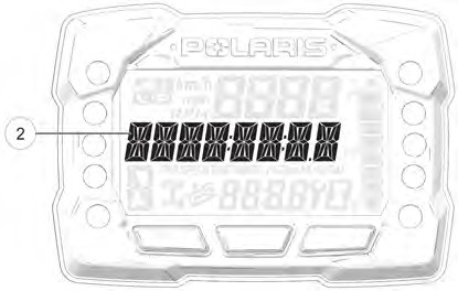
w Display Area 2 |
This area displays odometer, trip meter, trip meter 2, voltage, engine temperature, engine hour meter, programmable service hour interval, ground speed, engine RPM, geofence status, or speed limit status. Press the mode button on the left hand control to toggle through the available options. |
|
e Display Area 1 |
This area displays engine RPM, ground speed, or coolant temperature. |
|
r Fuel Gauge |
The segments of the fuel gauge show the level of fuel in the fuel tank. When the last segment clears, a low fuel warning is activated. All segments including the fuel icon will flash. Refuel immediately. |
|
t Service Indicator |
A flashing wrench symbol alerts the operator that the preset service interval has been reached. Your POLARIS dealer can provide scheduled maintenance. See page 74 for more information. |
|
y Clock (if equipped) |
The clock displays time in a 12-hour or 24-hour format. |
|
u AWD Indicator |
Segments of the indicator illuminate based on drive mode engaged. |
INDICATOR LAMPS
|
INDICATOR |
ICON |
FUNCTION |
|
Check Engine |
|
This indicator appears if an EFI-related fault occurs. Do not operate the vehicle if this warning appears. Serious engine damage could result. Your authorized POLARIS dealer can assist. |
|
EPS Warning (if equipped) |
|
This indicator illuminates when a fault has occurred in the EPS system. Your authorized POLARIS dealer can assist. EPS operation is possible with key on/engine off for up to 5 minutes. |
|
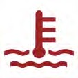
Engine Hot |
|
This lamp illuminates to indicate an overheated engine. If the indicator flashes, a severe overheating condition exists. |
|
Neutral |
|
This lamp illuminates when the transmission is in neutral and the ignition key is in the ON position. |
|
High Beam |
|
This lamp illuminates when the headlamp switch is set to high beam. |
|
Performance Limited |
|
On models equipped with a low speed limiter, indicator light will remain on when low speed limiter is active. Lamp illuminates when Geofencing or max speed is enabled. Lamp remains off when Geofencing and max speed settings are disabled. |


NO BUTTON GAUGE
Some Sportsman models are equipped with a no-button gauge. This gauge style does not come equipped with a clock feature. Other available features may vary.
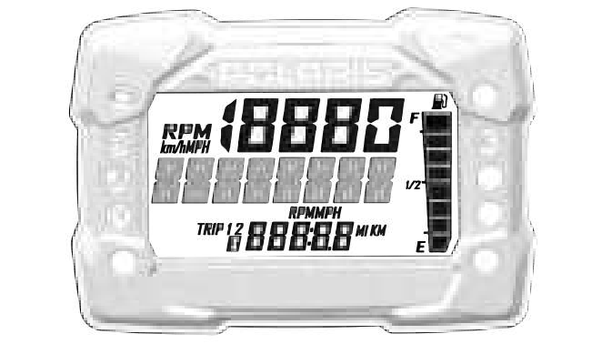
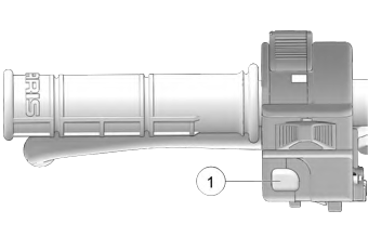 To toggle through available features, press Reverse Override / Mode Button q from the left hand controls. For the full list of available features, see the Display Area 2 section of this chapter.
To change between RPM and MPH, press the Reverse Override / MODE button to cycle to the RPM feature.
NOTICE
DISPLAY AREA 1
 Pressing the MODE button will change the information displayed in Area 1 q.
|
DISPLAY AREA 1 |
FUNCTION |
|
Speed |
The vehicle’s speed will be displayed in mph, or km/h. |
|
Engine Temperature |
The vehicle’s current engine temperature will be displayed. |
|
RPM |
The vehicle’s RPM will be displayed. |
DISPLAY AREA 2
 Toggle the Up/Down buttons to change the information displayed in Area 2 w.
|
DISPLAY AREA 2 |
FUNCTION |
|
Odometer |
The vehicle’s odometer reading will be displayed. |
|
Engine Temperature |
The vehicle Engine Temperature will be displayed. |
|
Trip 1 |
The vehicle Trip 1 mileage will be displayed. |
|
Trip 2 |
The vehicle Trip 2 mileage will be displayed. |
|
RPM |
The vehicle RPM will be displayed. |
|
Voltage |
The vehicle’s current battery voltage will be displayed. |
|
Speed |
The vehicle’s current speed will be displayed. |
|
Engine Hours |
The vehicle’s engine hours will be displayed. |
|
Service Hours |
The vehicle’s service hours will be displayed. |
OPTIONS MENU
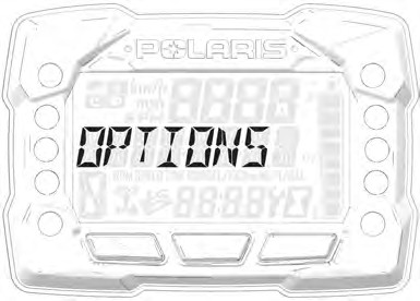 From the options menu you can view diagnostic codes, access the advanced menu, set the clock, and much more. For a full list of available options see below.
To enter the Options Menu, press and hold the MODE button.
|
OPTIONS MENU |
NOTES |
|
Electronic Power Steering (EPS) |
Turn EPS feature on/off and set between high, medium, or low. |
|
Diagnostic Codes |
Only displays if fault codes are present or stored |
|
Advanced Menu (if equipped) |
Set maximum speed, and geofencing settings. |
|
Units – Distance |
Select MPH or KPH |
|
Units – Temp |
Select between °F and °C |
|
Clock (if equipped) |
Select between 12H or 24H, and set time |
|
Backlight Color |
Select between Blue or Red |
|
Backlight Level |
Set backlight brightness level |
|
Service Hours |
View/Set Service hours |
|
Exit Menu |
Exit |
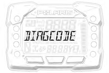
DIAGNOSTIC CODE
Diagnostic Code Screen will show available MIL that has come on during that ignition cycle.
 To access the Diagnostic Code Screen, do the following:
- Press and hold the MODE button to enter the Options Menu. “OPTIONS” will display on the screen for 3 seconds before showing first menu item.
- Select “Diagnostic Codes” from the Options Menu by pressing the MODE button.
Toggle the Up/Down Buttons to cycle through Code(s).
This option will only be available if a fault code was set or is active during the current ignition key ‘on’ cycle. Turning off the ignition will clear any save fault codes from the gauge.
NOTICE
 q Display area 1 will show FMI w Display area 2 will show SPN e Clock Area will show Count.
When the gauge is displaying a fault code, the warning telltale (check engine or EPS) will blink to indicate which controller set the fault code.
NOTICE
- To exit the Options Menu the user can select Exit Menu function from Options Menu, can hold Mode Button and exit out of Options Menu, or not press any button for 10 seconds, which will exit out of the Options Menu
- Press and hold the MODE button to enter the Options Menu.
“OPTIONS” will display on the screen for 3 seconds before showing first menu item.
NOTICE
- Select “ADVANCED MENU” by pressing the MODE button.
- Enter PIN.
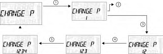
- Select “CHANGE PIN” from the Advanced Menu by pressing the MODE button.
Reference the image shown above:
q Press the MODE button.
w Toggle the Up/Down buttons to increase/decrease the first digit of the new PIN.
e With the desired first digit of the new PIN displayed, Press the MODE button which will set the digit and move to the 2nd digit.
r Toggle the Up/Down Buttons to increase/decrease the 2nd digit of the new PIN. Press MODE button to set 2nd digit and move on to the 3rd digit.
t Toggle the Up/Down Buttons to increase/decrease the 3rd digit of the new PIN. Press MODE button to set 3rd digit and move on to the 4th digit.
- Press the MODE button to set the 4th digit and exit.
- To exit the Advanced Menu the user can select Exit Menu function from Advanced Menu, can hold Mode button and exit out of Advanced Menu, or not press any button for 10 seconds, which will exit out of the Options Menu.
 UNIT SELECTION DISTANCE
-
- Press and hold the MODE button to enter the Options Menu.
“OPTIONS” will display on the screen for 3 seconds before showing first menu item.
NOTICE
-
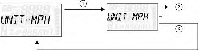
- Select “Units-Distance” from the Options Menu by pressing the MODE button.
Reference the image shown above:
q Press the MODE button.
w Toggle the Up/Down Buttons to change the units (MPH or KPH)
e With the correct unit displayed, Press the mode button which will set the unit and return to the Options Menu.
-
- To exit the Options Menu the user can select Exit Menu function from Options Menu, can hold Mode Button and exit out of Options Menu, or not press any button for 10 seconds, which will exit out of the Options Menu.
 UNIT SELECTION TEMPERATURE
- Press and hold the MODE button to enter the Options Menu.
“OPTIONS” will display on the screen for 3 seconds before showing first menu item.
NOTICE
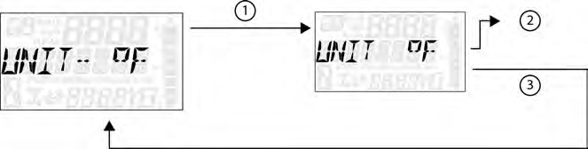
- Select “Units – Temp” from the Options Menu by pressing the MODE button. Reference the image shown above:
q Press the MODE button.
w Toggle the Up/Down Buttons to change the units (°F or °C)
e With the correct unit displayed, Press the mode button which will set the unit and return to the Options Menu.
- To exit the Options Menu the user can select Exit Menu function from Options Menu, can hold Mode Button and exit out of Options Menu, or not press any button for 10 seconds, which will exit out of the Options Menu.
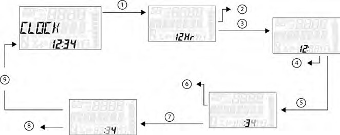 CLOCK (IF EQUIPPED)
-
- Press and hold the MODE button to enter the Options Menu.
“OPTIONS” will display on the screen for 3 seconds before showing first menu item.
NOTICE
-
- Select “Clock” from the Options Menu by pressing the MODE button. Reference the image shown above:
q Press the MODE button.
w Toggle the Up/Down Buttons to change the units (12H or 24H)
e With the correct unit displayed, Press the mode button which will set the unit.
r Toggle the Up/Down Buttons to change the units (Cycles Hours)
t With the correct unit displayed, Press the mode button which will set the unit.
y Toggle the Up/Down Buttons to change the units (Cycles 10s of Minutes)
u With the correct unit displayed, Press the mode button which will set the unit.
i Toggle the Up/Down Buttons to change the units (Cycles 1s of Minutes)
o With the correct unit displayed. Press the mode button which will set the unit and return to the Options menu.
-
- To exit the Options Menu the user can select Exit Menu function from Options Menu, can hold Mode Button and exit out of Options Menu, or not press any button for 10 seconds, which will exit out of the Options Menu.
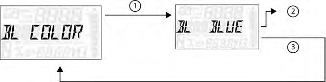 BACK LIGHT COLOR
- Press and hold the MODE button to enter the Options Menu.
“OPTIONS” will display on the screen for 3 seconds before showing first menu item.
NOTICE
- Select “Backlight Color” from the Options Menu by pressing the MODE button.
Reference the image shown above:
q Press the MODE button.
w Toggle the Up/Down Buttons to change the units (Blue or Red)
e With the correct unit displayed, Press the MODE button which will set the unit and return to the Options Menu.
- To exit the Options Menu the user can select Exit Menu function from Options Menu, can hold MODE Button and exit out of Options Menu, or not press any button for 10 seconds, which will exit out of the Options Menu.
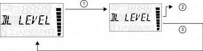 BACK LIGHT LEVEL
-
- Press and hold the MODE button to enter the Options Menu.
“OPTIONS” will display on the screen for 3 seconds before showing first menu item.
NOTICE
-
- Select “Backlight Level” from the Options Menu by pressing the MODE button.
Reference the image shown above:
q Press the MODE button.
w Toggle the Up/Down Buttons to change the units (Increase or De- crease Level)
e With the correct unit displayed, Press the MODE button which will set the unit and return to the Options Menu.
-
- To exit the Options Menu the user can select Exit Menu function from Options Menu, can hold MODE Button and exit out of Options Menu, or not press any button for 10 seconds, which will exit out of the Options Menu.
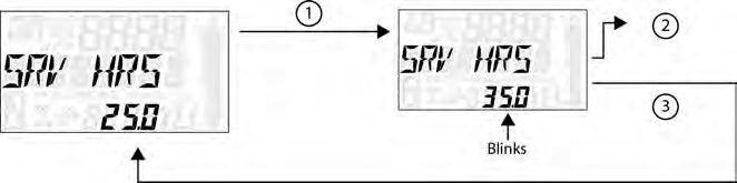 SERVICE HOURS
- Press and hold the MODE button to enter the Options Menu.
“OPTIONS” will display on the screen for 3 seconds before showing first menu item.
NOTICE
- Select “Service Hours” from the Options Menu by pressing the MODE button. Reference the image shown above:
q Press the MODE button.
w Toggle the Up/Down Buttons to change the units (0, 5, 10 – 95, 100)
e With the correct unit displayed, press the MODE button, which will set the unit and return you to the Options Menu.
To reset service hours after they have counted down to “0.0”, reselect the existing setpoint or select a new service hour value.
NOTICE
- To exit the Options Menu the user can select Exit Menu function from Options Menu, can hold MODE Button and exit out of Options Menu, or not press any button for 10 seconds, which will exit out of the Options Menu.
ELECTRONIC POWER STEERING (EPS) (IF EQUIPPED)
Electronic power steering (EPS), if equipped, engages when the ignition key is turned to the ON position. EPS remains engaged whether the vehicle is moving or idle. See the Instrument Cluster section for EPS Warning Indicator information.
Never switch EPS modes while the vehicle is in motion. Ensure the vehicle is fully stopped and no force is applied to the steering system before switching EPS modes.
NOTICE
 EPS has three modes: high, medium, low. To set the EPS mode, do the following.
-
- Stop the ATV and put it in PARK.
- Press and hold the MODE button to enter the Options Menu. “OPTIONS” will display on the screen for 3 seconds before showing the first menu item.
- Select “EPS” from the Options Menu by pressing the MODE button.
- Toggle the Up/Down Buttons to choose between the high, medium, and low modes.
- Press the MODE button to lock in the EPS setting.
AUXILIARY OUTLET
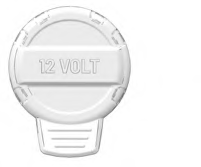 A 12-volt accessory outlet is located on the pod. Use the outlet to power an auxiliary light or other optional accessories or lights.
FUEL CAP
This vehicle is equipped with a digital fuel gauge that will indicate a low fuel condition. Refuel when the gauge indicates a low fuel condition.
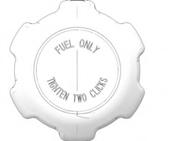 Always refuel with the engine stopped, and outdoors or in a well ventilated area. Refuel on a level surface.
Remove the fuel cap to add fuel to the fuel tank. Use unleaded gasoline with a minimum 87 octane rating (R+M)/2 or 91 RON minimum. Do not use fuel with ethanol content greater than 10 percent, such as E-85 fuel.
BATTERY CHARGE PORT
Your vehicle is equipped with a battery charge port q. The battery charge port allows you to quickly and easily connect a battery charger or maintainer to your vehicle’s battery. For more information see page 198.
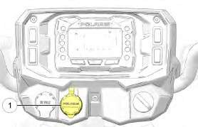
Image is for reference only. Your model might differ slightly.
NOTICE